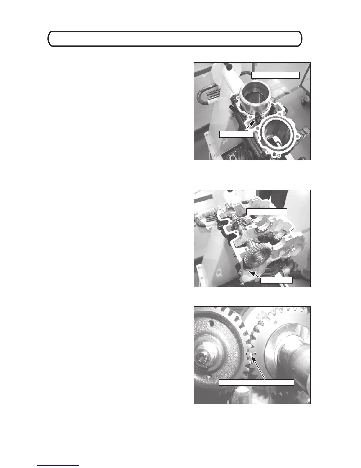
CHAIN GUIDE
RING COMPRESSOR
BALANCE SHAFT
DRIVE GEAR
SINGLE --DOT ALIGNMENT MARKS
ENGINE DISASSEMBLY / ASSEMBLY
4.44
2004 Four Stroke PWC Service Manual
Engine Assembly
9. Carefully install each piston assembly into the
cylinders. Take care in not scratching the cylinder bore.
10. Install the intake--side chain guide. Tighten fastener to
specification.
11. Carefully rotate engine 180_. Do not allow the pistons
to fall out of cylinders.
12. Select and install the connecting rod, crankshaft main
bearings, and balance shaft bearings. (Selection is
made using bearing selection process described in this
chapter.)
13. Coat all bearings and journals with engine oil. Install
water pump drive gear into crankcase.
14. Install the chain tensioner guide into the exhaust--side
of the crankcase. Tighten fastener to specification.
15. Install the balance shaft with the gear facing the front of
the engine.
NOTE: V erify bearing surfaces are centered within
journals.
16. Install crankshaft so that the two single--dot alignment
marks located on the balance shaft gear and
crankshaft gear face each other.
NOTE: V erify bearing surfaces are centered within
journals.
17. Coat bearing surfaces with engine oil.
 Loading...