8.11
ELECTRICAL
8
9923983 - 2012-2013 RZR 170 Service Manual
© Copyright 2012 Polaris Sales Inc.
RPM Limiter Specifications
NOTE: There are no timing advance marks stamped
on the flywheel to read with a timing light.
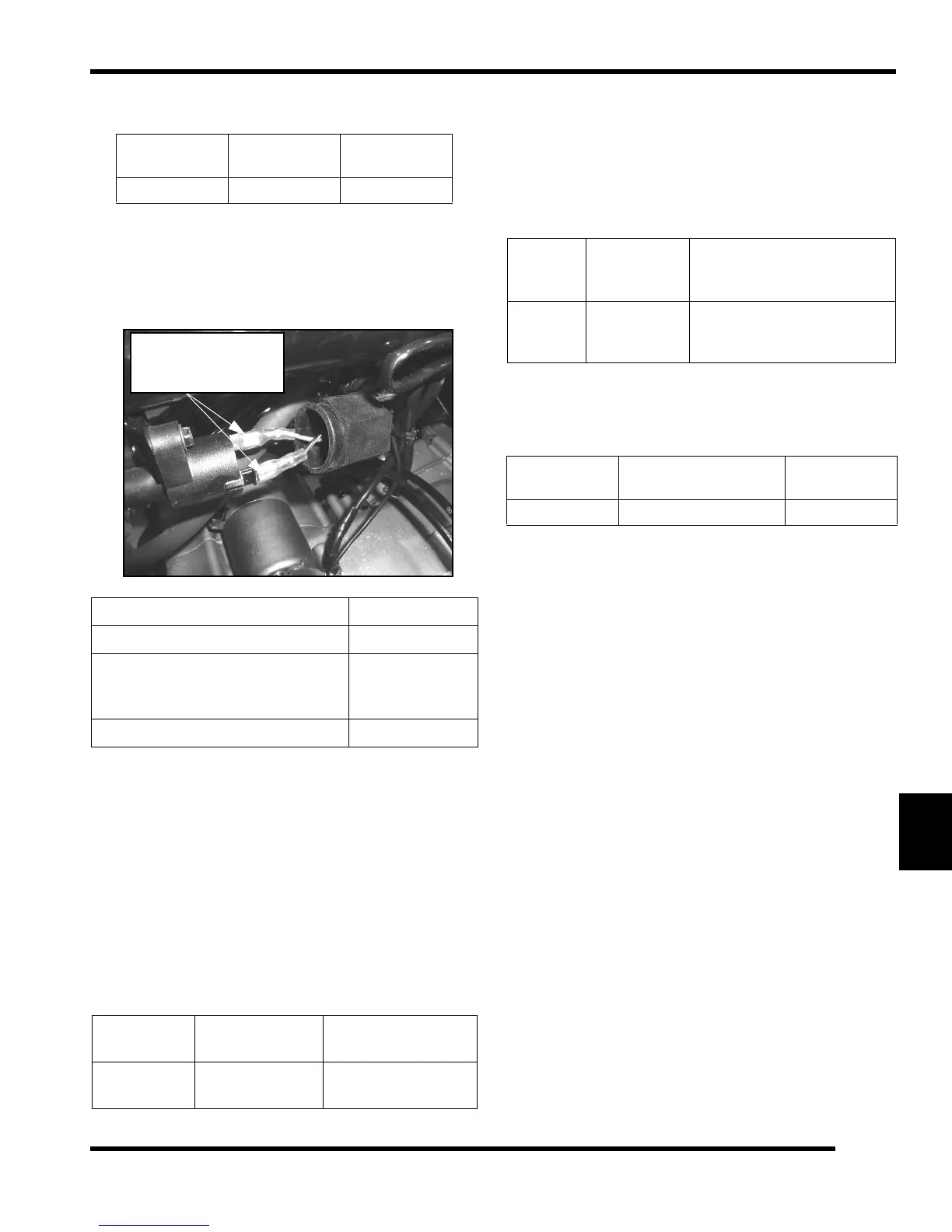
Ignition Coil Test
CDI Output Test
Using Peak Reading Adaptor
Re-connect all wires to the CDI box. Disconnect the
(BLACK/YEL) CDI output wire from ignition coil primary
terminal. Install the Peak Reading Adaptor (PV-39991) to
your meter and connect one meter lead to engine ground
and the other to the (BLACK/YEL) CDI output wire at the
ignition coil. Set meter to read DC Volts. Crank engine and
verify CDI output to the ignition coil. When finished,
reconnect CDI output wire to ignition coil.
Pulser Coil Output / Resistance Tests
Disconnect the 4-wire connector at the CDI box. Install the
Peak Reading Adaptor (PV-39991) to your meter and
connect one meter lead to the dark blue / black wire (DB/
YEL) and the other to engine ground. Set meter to read DC
Volts. Crank engine and verify pulser coil output.
If readings are within specifications, test the resistance
value of the pulser coil. When finished, reconnect the 4-
wire connector to CDI box.
Model Max RPM
Ignition
Timing
170cc 8000 N/A
Test Description Resistance
Ignition Coil Primary Winding 0.2 ± 20%
Ignition Coil Secondary Winding
(With Cap Installed)
(Without Cap Installed)
8 K ± 20%
3 K
± 20%
Spark Plug Resistor Cap 5 K
Output Test
Connect Meter
Leads To:
Reading
CDI Output
BLK/YEL to
Engine Ground
180 DC Volts ± 20%
Measure between
primary reading.
the two wire tabs for
Voltage
Test
Connect
Meter Leads
Between:
Reading
(With Peak Reading
Adapter)
Pulser
Coil
DB/YEL to
Engine
Ground
5 DC Volts minimum @
cranking RPM
Ohm Test
Connect
Meter Leads To:
W Reading
Pulser Coil DB/YEL to Black 151 ± 20%
 Loading...