24
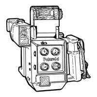
Shutter Mechanism
Note: Before performing any of the following steps, first remove from the Camera Body
theFront Panel, which contains the Shutter and Aperture Mechanisms (See
steps 1 - 7 in preceding Removing and Replacing Lenses, Tape Measure,
Shutter and Aperture Assemblies procedure).
Next, remove the Lens Board and Selector Board from the Aperture Mechanism
side of the Front Panel (See step 2 and 3 in preceding Aperture and Shutter
Mechanisms from the Front Panel procedure and Figure 3-11).
Shutter Blades
(Figures 3-12 and 3-13)
1. Remove the two pieces of tape securing the wires to the Shutter Board. Then
open the Cable Clamp and free the wires.
2. Unsolder the blue wires from the center terminal of the X (Sync) Socket.
Remove the hex nut and lug from the X (Sync) Socket.
3. From the Aperture mechanism side, remove the four screws A securing the
Shutter Assembly to the Shutter Plate (Figure 3-12).
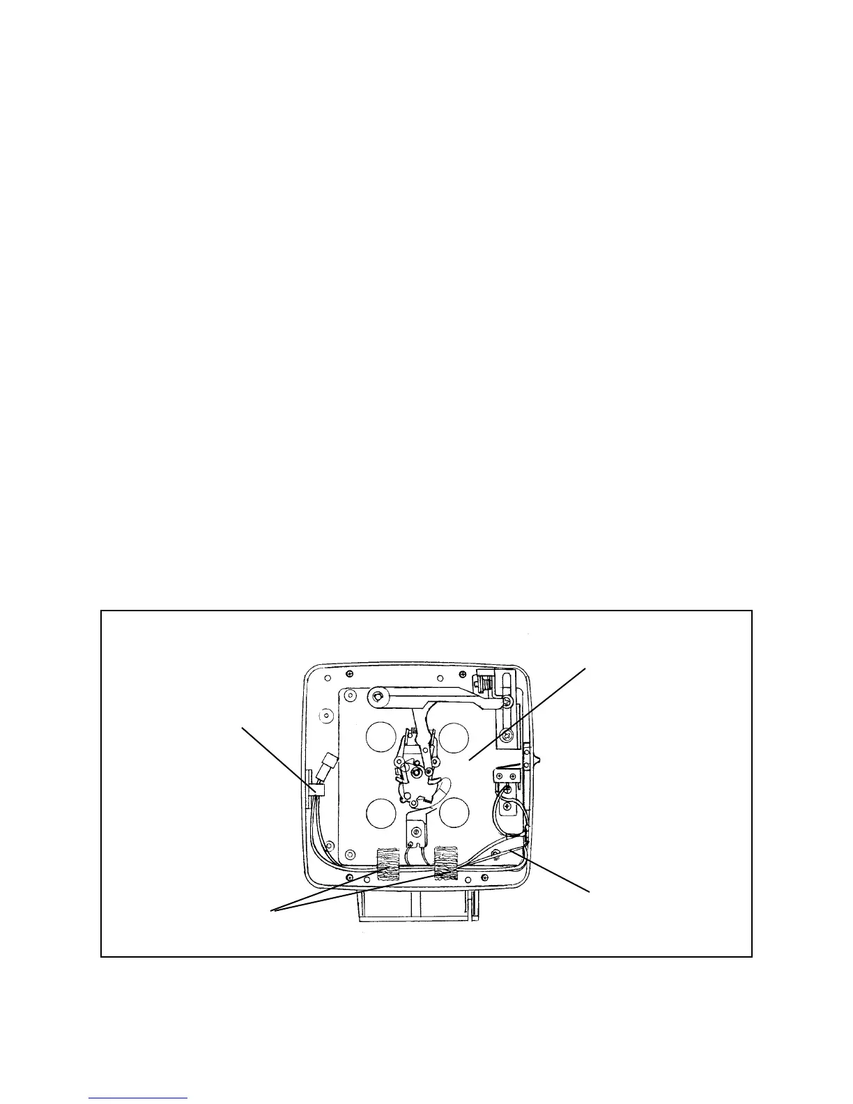
Figure 3-12. Shutter board sub-assembly
Cable Clamp
Shutter Board
Sub-Assy
Tape
Blue Wires
 Loading...