27
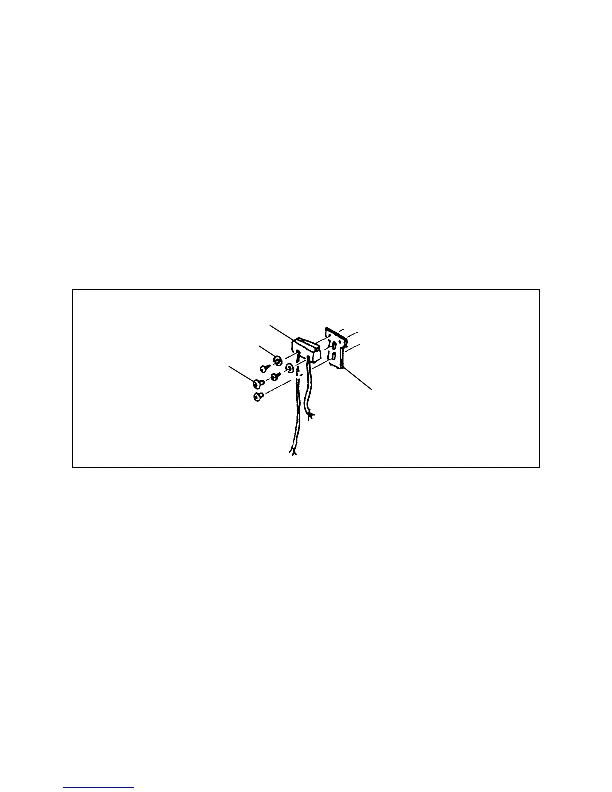
3. Microswitch
• Unsolder black and blue leads, remove two Switch mounting screws and
washers. If necessary, remove Switch Plate by removing its two mounting
screws.
• Re-assemble in reverse order. If Switch Plate has been disturbed,
temporarily remount it with rough side up, then mount Switch on Plate and
resolder wire leads. Check that Microswitch closes before Synchro Switch
closes, opens before Synchro Switch is tripped by return travel of Wheel
assembly when Shutter Button is released. When satisfied with position of
Microswitch, Loctite the mounting screws.
Figure 3-16. Microswitch
4. Shutter Drive (Release Lever, Pressure Lever and Wheel Assembly
• First remove the Wheel Spring by removing the E-Ring, Screw and Spacer
from its ends.
• Next remove the Release Lever by removing the E-Ring from its pivot post.
• Now remove the Pressure Lever and Release Lever Spring, below the
Release Lever, by removing the E-ring from the Lever pivot pin. Use care in
releasing tension of Spring.
• Unhook the Spring from the Left and Right Hooks, the E-Rings securing the
Hooks, and lift off both Hooks.
Microswitch
Washers
Screws
Switch Plate
 Loading...