25
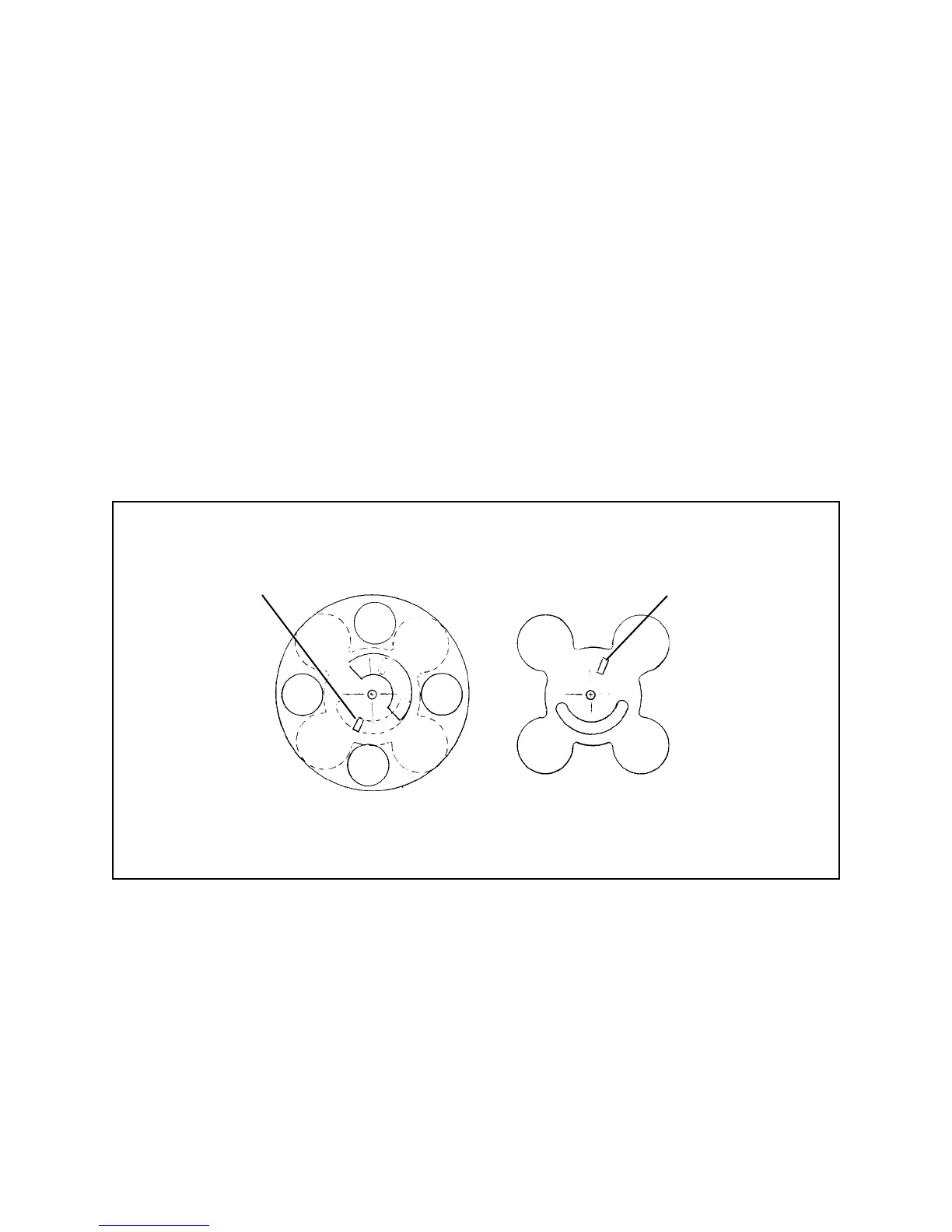
4. Carefully lift off the Shutter Board Sub-assembly, using care not to disturb the
position of the two Shutter Blades A and B beneath the Sub-Assembly
(Figure 3-13).
Caution
Before removing the Shutter Blades, note their order and orientation to
assure correct placement when reinstalling. Figure 3-13 shows their position
when the Shutter Board is removed.
Note: To re-assemble, perform steps 1 through 4 in reverse order. Position
Shutter Blades as shown in Figure 3-13. The pin on Wheel sub-assembly
must engage with the slot W on Blade B. The pin on the Pressure Lever
must engage with slot P on Blade A.
Figure 3-13. Shutter blade positions
Slot W
for
Wheel Pin
Slot P
for
Pressure Lever Pin
Blade B Blade A
 Loading...