29
Adjusting Flash Synchronization Contacts
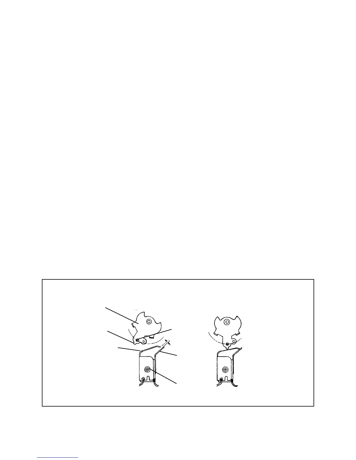
Synchro (X) Switch Contacts A and B should be normally open when no shutter action
occurs, and close momentarily when the Shutter is operated.
This can be checked by placing your index finger on the Wheel pin to prevent it from
rotating, as the Shutter Release Button is slowly depressed. Once the Shutter
mechanism is unlatched, allow the Wheel to rotate slowly and observe its cam action
on the upper contact leaf of the Switch. The Wheel should deflect the upper contact
leaf just enough to close and then open it.
If this normally open/close/open action does not occur, loosen the plastic screw slightly
at the center of the Switch and adjust the contacts appropriately. In the normally open
position, the gap between contacts should be 0.5 mm. Retighten the screw and when
Switch operation is correct, use a small amount of Loctite around the screw head to
secure it.
Caution
Do not overtighten screw and strip threads.
If wire leads have been removed, resolder them after the Switch is mounted on the
frame. Position Switch wiring as shown in Figure 3-18, and hold it in place with two
pieces of black tape 10 mm wide x 20 mm long, positioned 4 - 5 mm from the holes in
the Shutter Board Assembly.
Figure 3-18. Synchro (X) switch contact adjustment
Normally-Open Contacts
Wheel Latched
Contacts Closed by Shutter Release
Wheel Unlatched
Wheel
Pin
Lower Contact
Leaf B
Upper Contact
Leaf A
Plastic Screw
0.5mm
Cam
Lobe
 Loading...