QSW-4700 Series Switches Hardware Installation and Reference Guide
INSTALLING THE SWITCH
59
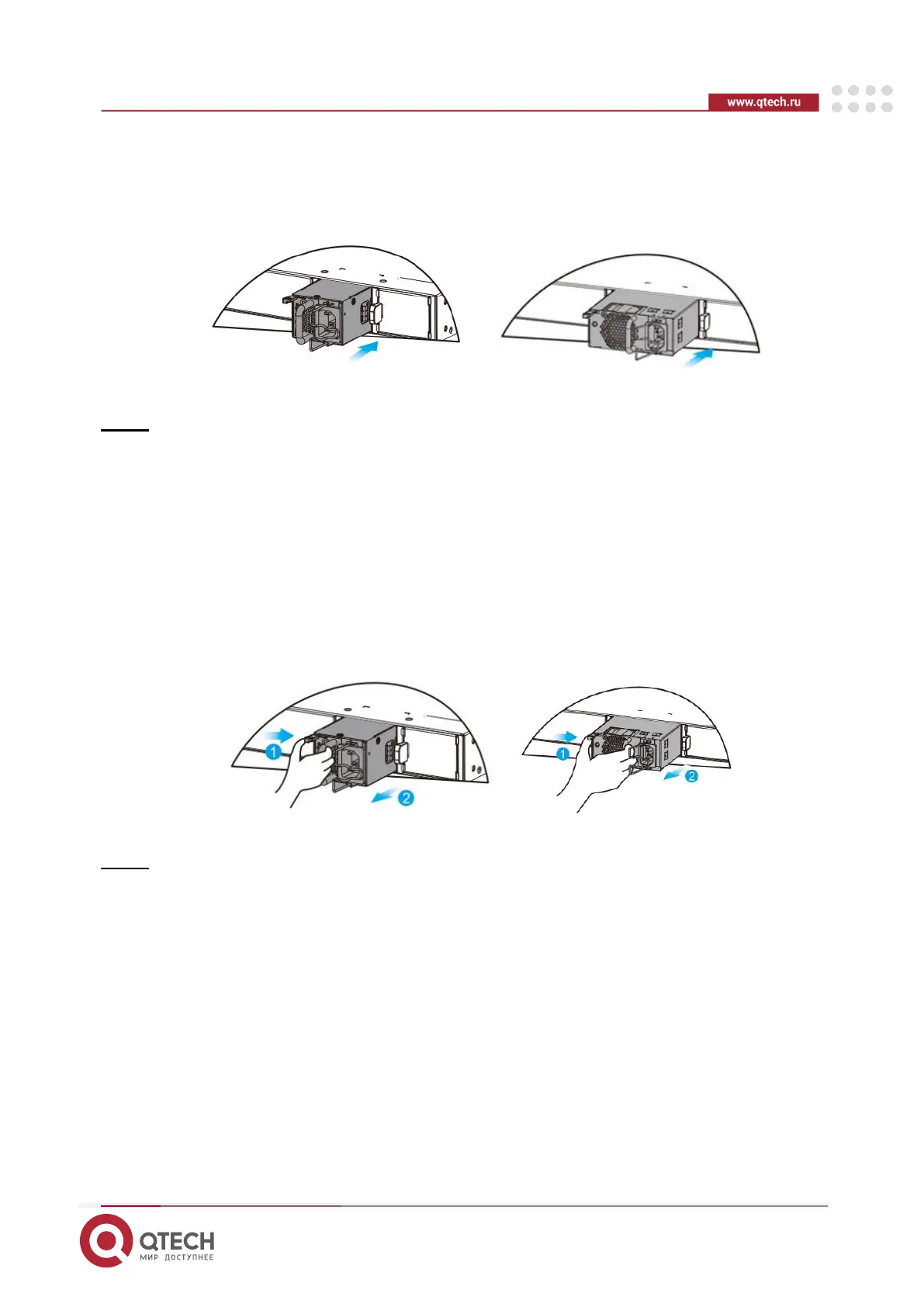
2. Remove the blank filler panel in the empty slot. Keep the module nameplate face
upward. Grasp the handle with one hand and place your other hand under the module
to support its weight. Slide the module all the way into the slot along the guide rail until
you feel the connector snap into place.
Figure 3-7 Installing the Module
Note:
• Slide the module into the slot. Verify that the power supply module is in the correct
orientation.
• If you find it difficult to fully insert the module, pull the module out, align it to the guide
rails and slide it into the slot again.
3.4.2. Removing the AC Power Supply Module
1. Press the latch on the module and grasp the handle with one hand. Place your other
hand under the module to support its weight. Pull the module fully out of the slot.
2. Install the filler panel in the empty slot. Put the removed module back into its packing
materials.
Figure 3-8 Removing the Module
Note:
• Pull the module out of the slot gently.
• Install the filler panel in the empty slot to allow for adequate airflow.
3.4.3. Installing the DC Power Supply Module
1. Remove the module from its packing materials and make sure the input specifications
meet requirements.
2. Remove the blank filler panel in the empty slot. Keep the module nameplate face
upward. Grasp the handle with one hand and place your other hand under the module
to support its weight. Slide the module all the way into the slot along the guide rail until
you feel the connector snap into place. The two screws of the DC power supply are
the input of the power supply. Remove the protective cover of the power input
terminal, loosen the screw, and connect the terminals of the power cord. From left to
right, they are blue and red, and then cover the terminal protective cover.
 Loading...