ATA Bus Interface and ATA Commands
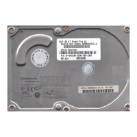
Quantum Fireball Plus AS 10.2/20.5/30.0/40.0/60.0 GB AT 6-13
Notes:
Notes:Notes:
Notes:
1. All signal transitions for a timing parameter will be measured at the connector
specified in the measured location column. For example, in the case of t
RFS
,
both STROBE and DMARDY- transitions are measured at the sender
connector.
2. The parameter t
LI
shall be measured at the connector of the sender or
recipient that is responding to an incoming transition from the recipient or
sender respectively. Both the incoming signal and the outgoing response
will be measured at the same connector.
3. The parameter t
AZ
will be measured at the connector of the sender or
recipient that is releasing the bus.
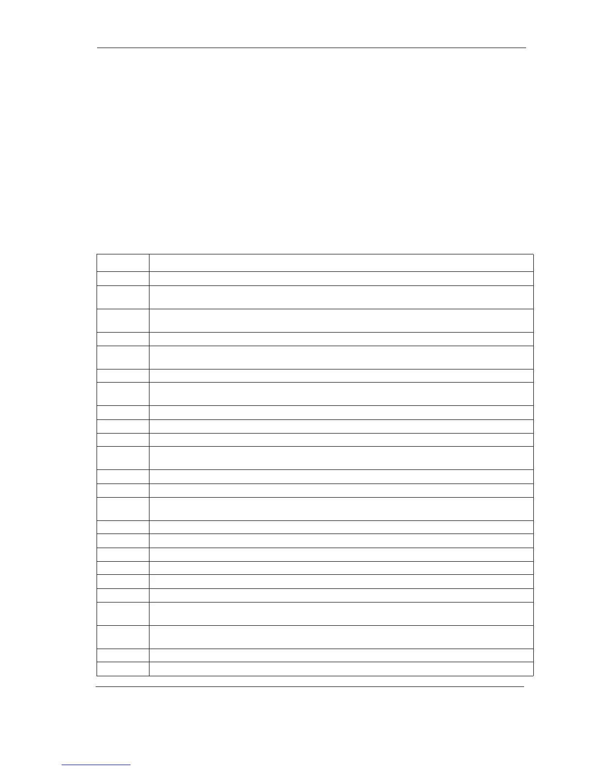
Table 6-8
Table 6-8 Table 6-8
Table 6-8 Ultra DMA Data Burst Timing Descriptions
Name
NameName
Name Comment
Comment Comment
Comment
t
2CYCTYP
Typical sustained average two cycle time
t
CYC
Cycle time allowing for asymmetry and clock variations (from STROBE edge to STROBE
edge)
t
2CYC
Two cycle time allowing for clock variations (from rising edge to next rising edge or
from falling edge to next falling edge of STROBE)
t
DS
Data setup time at recipient (from data valid until STROBE edge) (see notes 2,5)
t
DH
Data hold time at recipient (from STROBE edge until data may become invalid) (see
note 2,5)
t
DVS
Data valid setup time at sender (from data valid until STROBE edge) (see note 3)
t
DVH
Data valid hold time at sender (from STROBE edge until data may become invalid) (see
note 3)
t
CS
CRC word setup time at device (see note 2)
t
CH
CRC word hold time device (see note 2)
t
CVS
CRC word valid setup time at host (from CRC valid until DMACK- negation) (see note 3)
t
CVH
CRC word valid hold time at sender (from DMACK- negation until CRC may become
invalid) (see note 3)
t
ZFS
Time from STROBE output released-to-driving until the first transition of critical timing.
t
DZFS
Time from data output released-to-driving until the first transition of critical timing.
t
FS
First STROBE time (for device to first negate DSTROBE from STOP during a data in
burst)
t
LI
Limited interlock time (see note 1)
t
MLI
Interlock time with minimum (see note 1)
t
UI
Unlimited interlock time (see note 1)
t
AZ
Maximum time allowed for output drivers to release (from asserted or negated)
t
ZAH
Minimum delay time required for output
t
ZAD
drivers to assert or negate (from released)
t
ENV
Envelope time (from DMACK- to STOP and HDMARDY- during data in burst initiation
and from DMACK to STOP during data out burst initiation)
t
RFS
Ready-to-final-STROBE time (no STROBE edges shall be sent this long after negation of
DMARDY-)
t
RP
Ready-to-pause time (that recipient shall wait to pause after negating DMARDY-)
t
IORDYZ
Maximum time before releasing IORDY
 Loading...