ATA Bus Interface and ATA Commands
6-20 Quantum Fireball Plus AS 10.2/20.5/30.0/40.0/60.0 GB AT
Figure 6-12
Figure 6-12 Figure 6-12
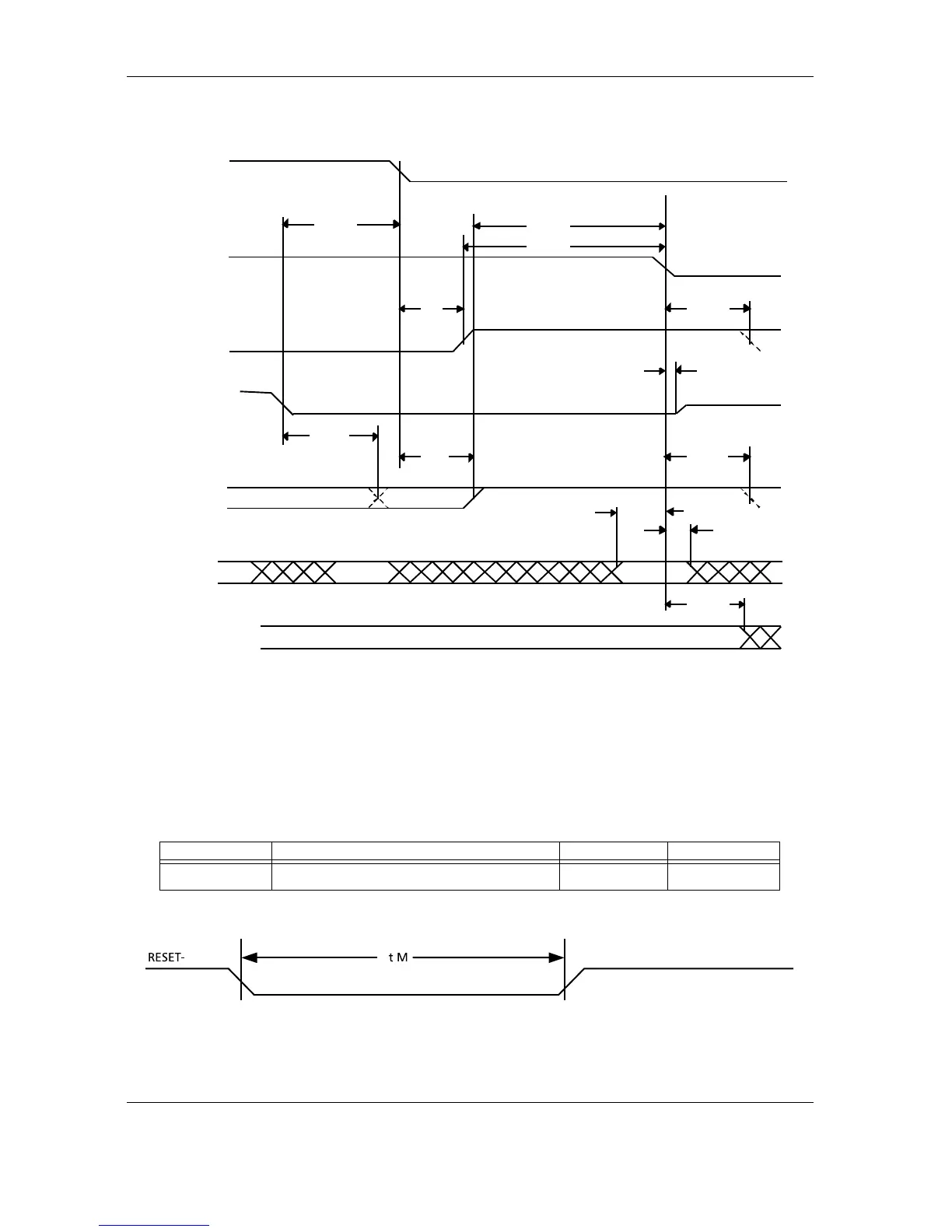
Figure 6-12 Device Terminating a Data out Burst
6.4.2.3
6.4.2.36.4.2.3
6.4.2.3 Host Interface RESET Timing
Host Interface RESET TimingHost Interface RESET Timing
Host Interface RESET Timing
The host interface RESET timing shown in Table 6-9 is in reference to signals at 0.8
volts and 2.0 volts. All times are in nanoseconds, unless otherwise noted. Figure 6-
13 provides a timing diagram.
Table 6-9
Table 6-9 Table 6-9
Table 6-9
Host Interface RESET Timing
Figure 6-13
Figure 6-13 Figure 6-13
Figure 6-13 Host Interface RESET Timing
SYMBOL DESCRIPTION MINIMUM MAXIMUM
tM
RESET– Pulse width
25 —
DMARQ
(device)
DMACK-
(host)
STOP
(host)
DDMARDY-
(device)
HSTROBE
(host)
DD(15:0)
(host)
DA0, DA1, DA2,
CS0-, CS1-
Tack
Tmli
Tdvs
Tli
Tli
Tack
CRC
Tdvh
Tack
Tiordyz
TmliTrp
Trfs
 Loading...