LPWA Module Series
BG95 Hardware Design
BG95_Hardware_Design 35 / 80
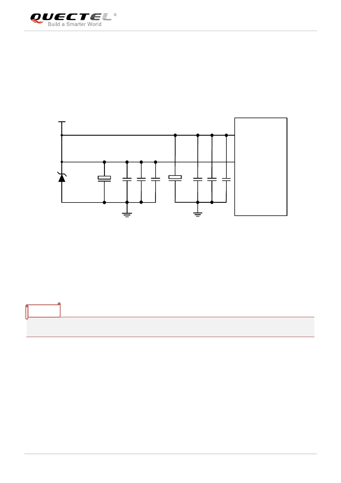
a single voltage source and can be expanded to two sub paths with star structure. The width of VBAT_BB
trace should be no less than 0.5mm, and the width of VBAT_RF trace should be no less than 2mm. In
principle, the longer the VBAT trace is, the wider it will be.
In addition, in order to get a stable power source, it is suggested to use a TVS with low leakage current
and suitable reverse stand-off voltage, and also it is recommended to place it as close to the VBAT pins as
possible. The following figure shows the star structure of the power supply.
Module
VB AT_RF
VB AT_BB
VB AT
C1
100uF
C6 C7 C8
+
+
C2
100nF
C5
C3
33pF
C4
10pF
D1
TVS
100uF
100nF
33pF
10pF
Figure 5: Star Structure of the Power Supply
3.5.3. Monitor the Power Supply
AT+CBC* command can be used to monitor the VBAT_BB voltage value. For more details, please refer
to document [2].
“*” means under development.
3.6. Turn on and off Scenarios
3.6.1. Turn on Module Using the PWRKEY Pin
The following table shows the pin definition of PWRKEY.
NOTE

 Loading...


