EasyManuals Logo
Home>Quectel>Control Unit>EM06 Series

Quectel EM06 Series User Manual

Quectel EM06 Series
70 pages
To Next Page IconTo Next Page
To Previous Page IconTo Previous Page
Page #31 background imageLoading...
Page #31 background image
LTE-A Module Series
EM06 Series Hardware Design
EM06_Series_Hardware_Design 30 / 69
short-circuited to ground when no (U)SIM card inserted. When a (U)SIM card gets inserted, the pin will
change from low to high level with a rising edge indicating the insertion of a (U)SIM card; when the card is
removed, the pin will return to low level with a falling edge indicating the removal of card.
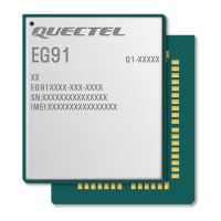
The following figure shows a reference design of the (U)SIM interface with normally closed (U)SIM card
connector (CD switch closed).
Module
USIM_VDD
USIM_RST
USIM_CLK
USIM_DATA
USIM_DET
22R
22R
22R
100 nF
(U)SIM Card Connector
GND
33 pF
33 pF 33 pF
VCC
RST
CLK
IO
VPP
GND
GND
USIM_VDD
15K
GND
CD GND
Switch
Figure 13: Reference Design of (U)SIM Interface with Normally Closed (U)SIM Card Connector
Normally Closed (U)SIM Card Connector:
When the (U)SIM card is absent, the switch is closed and USIM_DET is at low level.
When the (U)SIM card is inserted, the switch is open and USIM_DET is at high level.
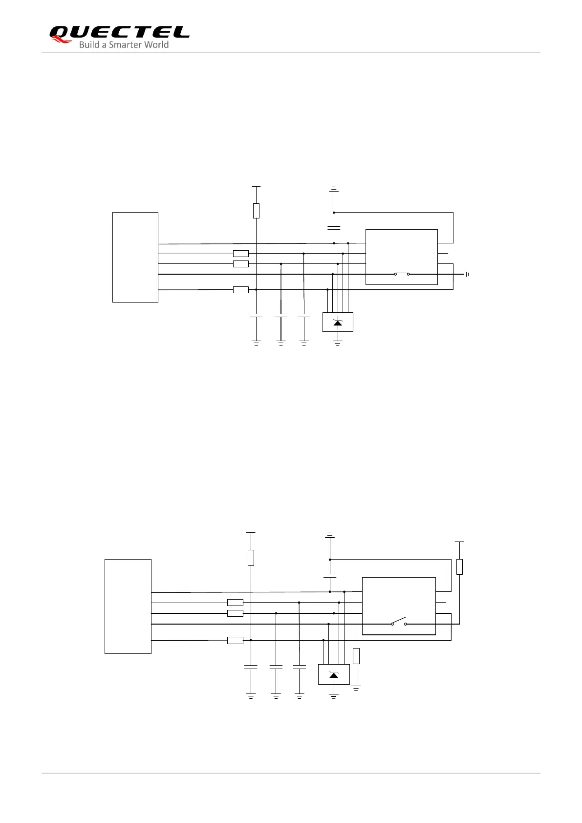
The following figure shows a reference design of (U)SIM interface with normally open (U)SIM card
connector.
Module
USIM_VDD
USIM_RST
USIM_CLK
USIM_DATA
USIM_DET
22R
22R
22R
100 nF
(U)SIM Card Connector
GND
33 pF
33 pF
33 pF
VCC
RST
CLK
IO
VPP
GND
GND
USIM_VDD
15K
GND
CD
1.8 V
4.7K
33K
GND
Switch
Figure 14: Reference Design of (U)SIM Interface with Normally Open (U)SIM Card Connector

Questions and Answers:

Question and Answer IconNeed help?

Do you have a question about the Quectel EM06 Series and is the answer not in the manual?

Quectel EM06 Series Specifications

General IconGeneral
BrandQuectel
ModelEM06 Series
CategoryControl Unit
LanguageEnglish

Related product manuals