LTE-A Module Series
EM06 Series Hardware Design
EM06_Series_Hardware_Design 31 / 69
Normally Open (U)SIM Card Connector:
⚫ When the (U)SIM card is absent, the switch is open and USIM_DET is at low level.
⚫ When the (U)SIM card is inserted, the switch is closed and USIM_DET is at high level.
If the (U)SIM card detection function is not needed, please keep USIM_DET unconnected. A reference
circuit for (U)SIM interface with a 6-pin (U)SIM card connector is illustrated in the following figure.
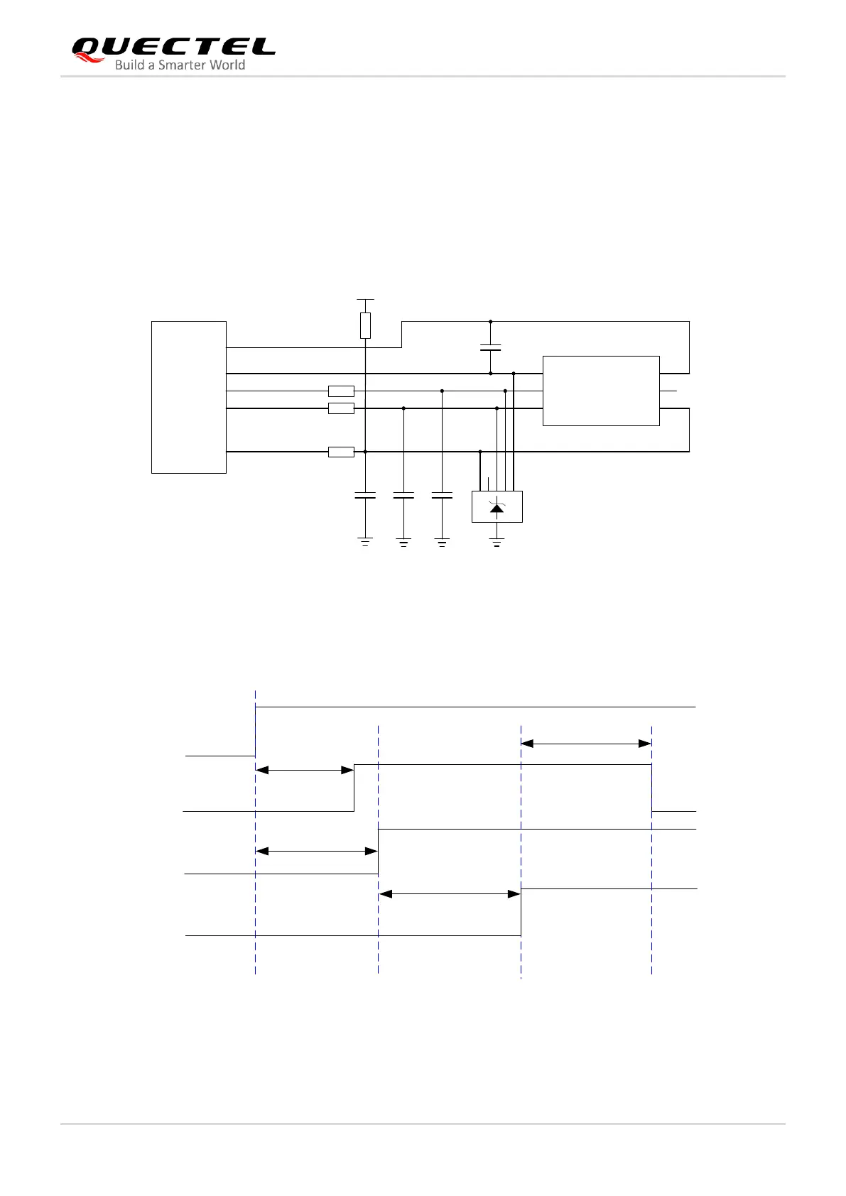
Figure 15: Reference Design of (U)SIM Interface with a 6-Pin (U)SIM Card Connector
The timing of (U)SIM is illustrated by the following figure.
USIM_VDD
21.7 ms
USIM_DATA
USIM_CLK
USIM_RST
USIM_CLK
ATR
tb ta + 52 us
ta 1.5 ms
0.1 ms tc 10 ms
Notes:
1. ta is the time interval between USIM_VDD HIGH level and USIM_CLK HIGH level.
2. tb is the time interval between USIM_VDD HIGH level and USIM_DATA HIGH level.
3. tc is the time interval between USIM_RST HIGH level and answer on USIM_DATA.

 Loading...