14
NOTICE
• The installer MUST test for proper connection and functionality of the operator and its accessories
before leaving the job site.
• The installer should also perform a demonstration for the end-user.
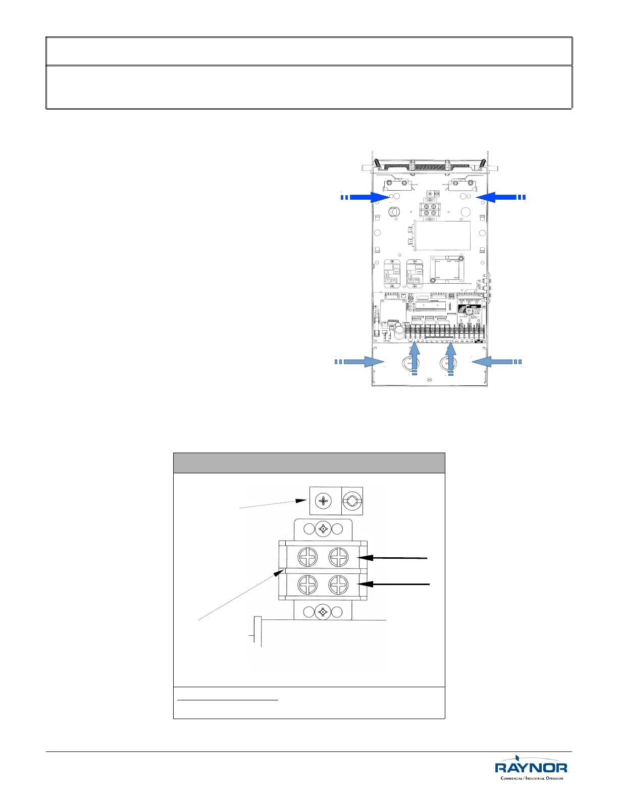
6.1 Low Voltage (Controls) and High Voltage (Power) Connections
1. Route the power line wires either from
the right or from the left of the control
box, as shown in Figure 6.
2. Route all low voltage control wires, as
shown in Figure 6. KEEP LOW
VOLTAGE WIRES SEPARATE FROM
LINE VOLTAGE WIRES.
3. USE COPPER CONDUCTORS ONLY.
6.2 Main Power Supply Connection
Single-Phase (115V)
Correct motor rotation: Switch the BLUE and RED wires on
the capacitor.
For technical support, please call 1-800-4-Raynor (1-800-472-9667) or visit www.raynor.com
Ground Lug
LIVE
Figure 6 - Low Voltage
(Controls) and High Voltage
(Power) Connections
Power
Control
Power Terminal Block
NEUTRAL
 Loading...