17
6.5 Optional Accessory Connections
NOTICE
• If the door is controlled by any device other than a constant pressure push-button station on close,
including a timer-to-close, an entrapment protection device must be connected.
• Photoelectric cells must be installed facing each other across the door's path within 6” (15 cm) of the
plane of the door and the beam no more than 5-3/4” (14.6 cm) above the floor.
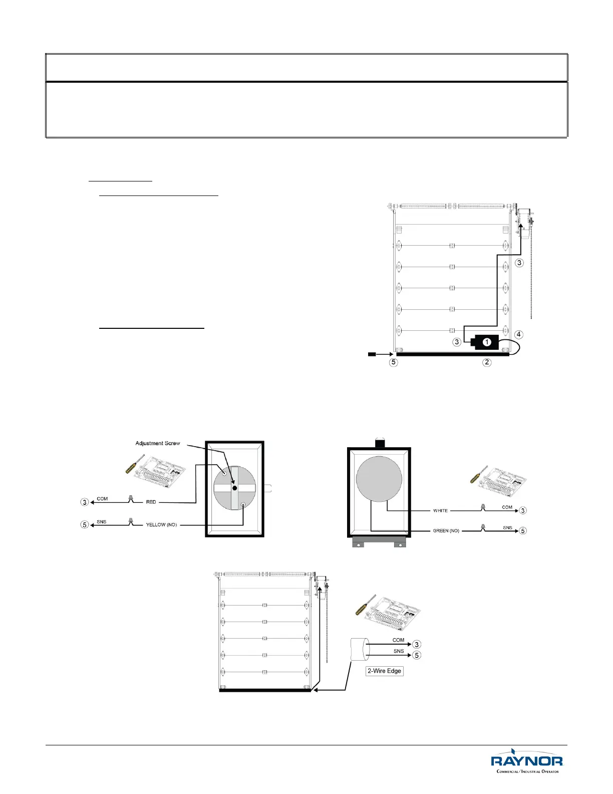
6.5.1 Reversing Edge Device (Non-Monitored)
Installation
Pneumatic Sensing Edge
1. Place the air switch in position, refer to Figure 11.
2. Place the air hose in position.
3. Use a coil cord or take-up reel to connect the air
switch to the operator terminals. Install electric
wires according to Figure 12 or Figure 13.
4. Connect one end of the air hose to the air
switch.
5. Place the air plug in the other end of the air
hose.
Electric Sensing Edge
1. Place the junction box in position, refer to Figure 11.
2. Place the sensing edge in position.
3. Use a coil cord or take-up reel to connect the
sensing edge wires to the operator terminals.
Install electric wires according to Figure 14.
4. Connect the sensing edge to the junction box.
5. N/A
Figure 12 - AIRSWITCH Connection
Figure 13 - AIRSWITCH Connection
Figure 14 - Electric Reversing Edge Connection
For technical support, please call 1-800-4-Raynor (1-800-472-9667) or visit www.raynor.com
Figure 11 - Reversing Edge Connection
 Loading...