20
7.2 On-Board LED Monitoring Status
The electronic control board's LEDs help with wiring and troubleshooting diagnostics. Every LED indicates the status
of the door. BOARD 070M has a non-volatile memory and the LEDs return to their initial state after a power
interruption. Refer to Figure 17, p.19 as reference.
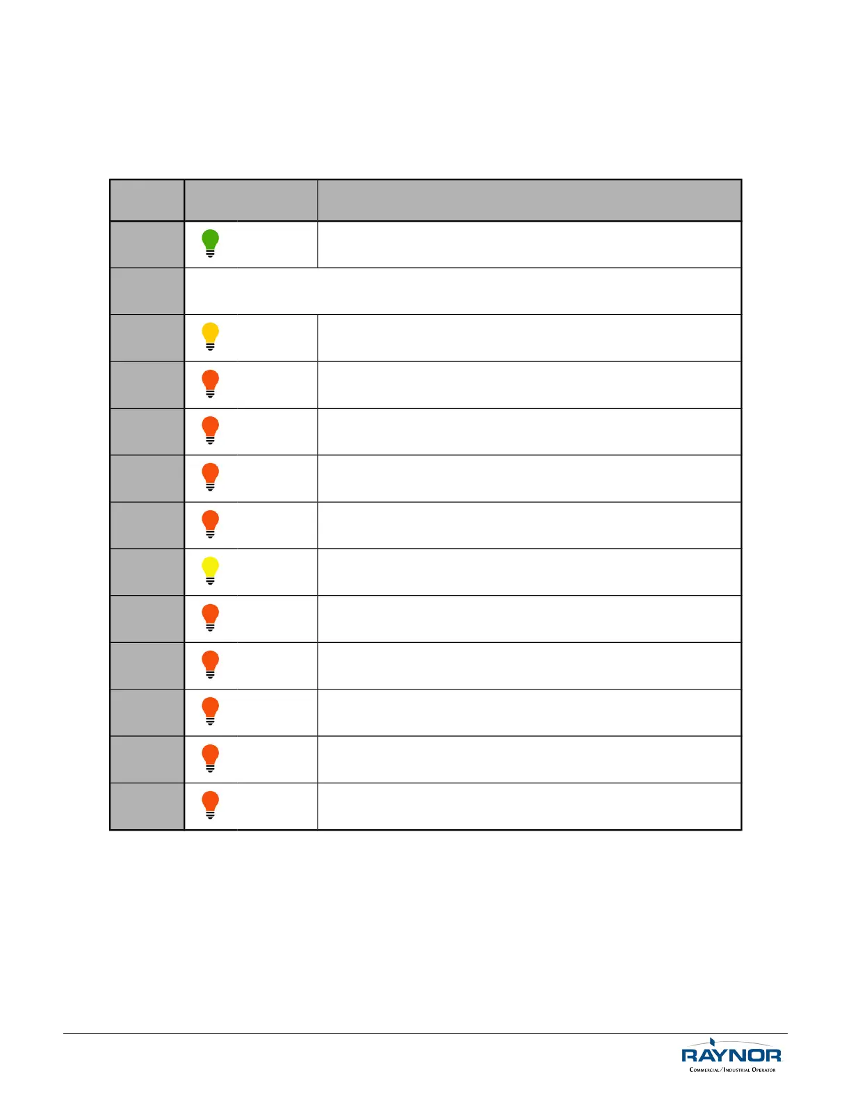
Table 4 - LED Monitoring Status
LED LED ON Functions
D1 GREEN Indicates presence of 24VDC.
D2 / D3 Refer to Table 5, p.21 as reference.
D4 ORANGE
Indicates monitored photo cell activation or absence of monitored
photo cell or defective photo cell.
D5 RED
Only when single-button radio transmitter is activated
(stays ON for +/- 1 sec).
D6 RED When reversing or sensing edge is activated.
D7 RED When close command is activated.
D8 RED When open command is activated.
D9 YELLOW
Indicates that the stop button is connected and hoist or disconnect
switch is not engaged.
D10 RED
When inductive loop (Terminal #12) is activated (when loop is
activated, door can be closed only by constant pressure).
D11 RED When external timer to close defeat switch is activated (if used).
D12 RED When open limit switch is activated.
D13 RED When external mid-stop limit switch is activated (if used).
D14 RED When close limit switch is activated.
For technical support, please call 1-800-4-Raynor (1-800-472-9667) or visit www.raynor.com
 Loading...