SCRATCH-PAD
MEMORY
(Cont'd)
TRANSLATION
MEMORY
System
Structure
5.
Program Counter - A
Program
Counter
for
each processor
state
contains
the
main
memory
address
of
the
next
instruction
to be
executed,
the
condition code,
the
instruction
length code,
and
the
program
mask.
6.
Input/Output Channel Registers - A
set
of
four
registers
for
each
selector channel controls
input/output
operation. A
set
of
four
registers
for
the
multiplexor channel controls
initiation
and
ter-
mination
of
input/output
operations on
the
multiplexor channel.
7.
Floating-Point Registers -
Four
floating-point
registers
(each is
two words long)
are
used in floating-point
arithmetic.
8.
Interrupt Flag Register - One
Interrupt
Flag
register
is provided.
When
an
interrupt
condition occurs, a
bit
associated
with
this
con-
dition is
set
in
the
Interrupt
Flag
register.
• The
Translation
Memory is a magnetic
storage
device consisting of
512
halfwords
(1,024
bytes),
the
cycle time
of
which is 300 nanoseconds.
Each
halfword
(two bytes)
in
the
translation
memory is uniquely addressed
and
contains a
translation
table element which is used
in
translating
virtual
addresses to actual addresses (see figure
2).
The
translation
table which is
maintained
in
the
translation
memory
is loaded
and
stored
from
and to
main
memory by special EO
(Elementary
Operation) routines.
It
is addressed
during
each
main
memory address-
ing
cycle when
translation
is required. Address
translation
does
not
require
additional
instruction
time
from
that
required by
the
basic 70/45
timing;
however, staticizing time
for
the
SS-Format
Load Multiple
and
Execute
instructions
is increased when
operating
in
70/46 Mode.
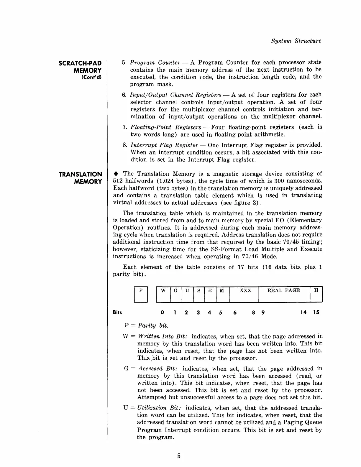
Each
element
of
the
table consists
of
17
bits
(16
data
bits
plus 1
parity
bit).
Bits
xxx
REAL
PAGE
o
2 3 4 5
6 8 9
14
15
P = Parity bit.
W = Written Into
Bit:
indicates, when set,
that
the
page addressed in
memory by
this
translation
word
has
been
written
into. This
bit
indicates, when reset,
that
the
page
has
not
been
written
into.
This \bit is
set
and
reset
by
the
processor.
G
= Accessed Bit: indicates, when set,
that
the
page addressed in
memory by
this
translation
word
has
been accessed (read,
or
written
into).
This
bit
indicates, when reset,
that
the
page
has
not
been accessed. This
bit
is
set
and
reset
by
the
processor.
Attempted
but
unsuccessful access to a page does
not
set
this
bit.
U = Utilization
Bit:
indicates, when set,
that
the
addressed
transla-
tion word
can
be utilized.
This
bit
indicates, when reset,
that
the
addressed
translation
word
cannot'be
utilized
and
a
Paging
Queue
Program
Interrupt
condition occurs.
This
bit
is
set
and
reset
by
the
program.
5
 Loading...