R8C/1A Group, R8C/1B Group 16. Clock Synchronous Serial Interface
Rev.1.30 Dec 08, 2006 Page 230 of 315
REJ09B0252-0130
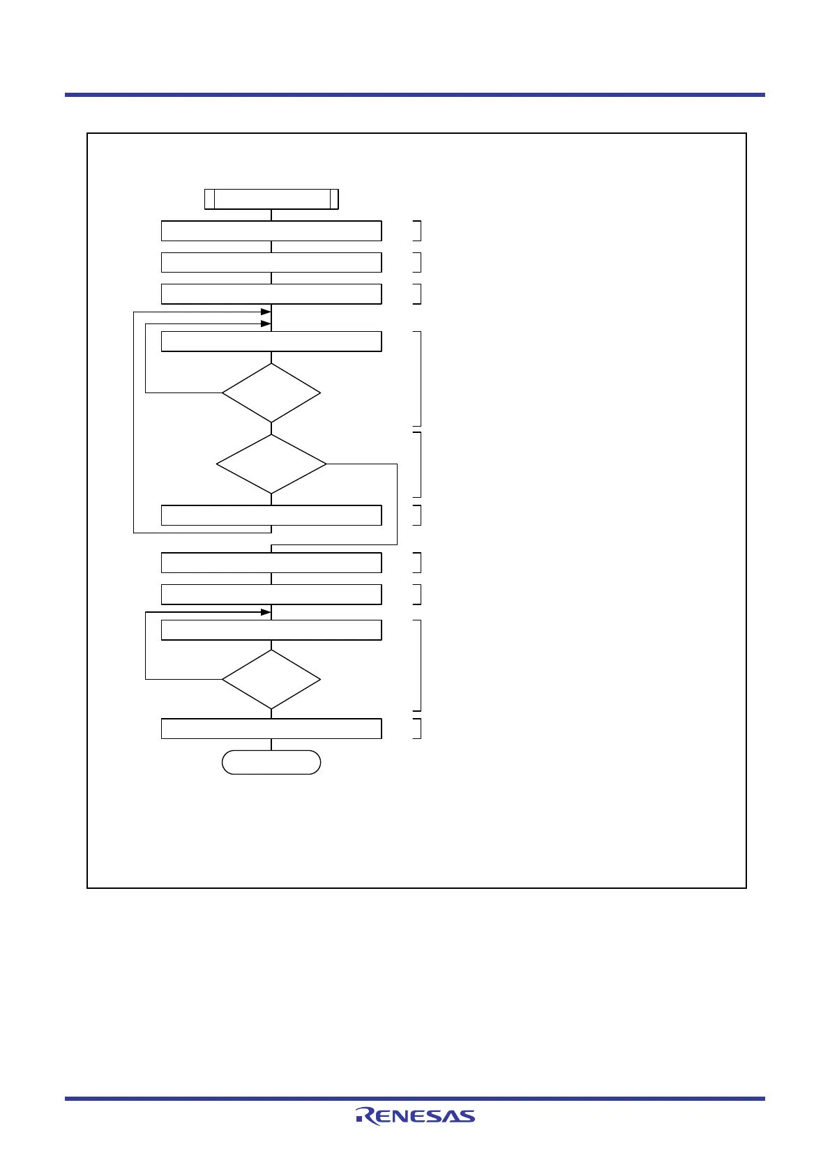
Figure 16.49 Example of Register Setting in Slave Receive Mode (I
2
C bus Interface Mode)
End
RDRF = 1 ?
Slave receive mode
No
Yes
(1) Set the AAS bit to 0.
(1)
(2) Set the ACKBT bit to the transmit device.
(3) Dummy read the ICDRR register
(4) Wait until 1 byte is received.
(5) Judge (last receive - 1).
(6) Read the receive data.
(7) Set the ACKBT bit of the last byte.
(1)
(8) Read the receive data of (last byte - 1).
(9) Wait until the last byte is received
(10) Read the receive data of the last byte.
Dummy read in ICDRR register
Read RDRF bit in ICSR register
Last receive
- 1 ?
(1)
(2)
(3)
(4)
(5)
(6)
(7)
(8)
(10)
(9)
ICIER register ACKBT bit ← 0
No
Yes
Read ICDRR register
ICIER register ACKBT bit ← 1
Read ICDRR register
Read RDRF bit in ICSR register
RDRF = 1 ?
Read ICDRR register
No
Yes
NOTE:
1. When receiving 1 byte, skip steps (2) to (6) after (1) and jump to processing step (7).
Processing step (8) is dummy read of the ICDRR register.
ICSR register AAS bit ← 0
 Loading...


