14
I-SCE (09-18) PN207697R9
Table 6. Parts List for Horizontal Vent Terminal/Combustion Air Package (Option CC6)
PN Description Qty
205883 Kit, Horizontal Vent 1
205885 Assembly, Concentric Adapter Box (see Figure 10) 1
53316 Assembly, Screened Exhaust (see Figure 13) 1
205894 Inlet Guard (see Figure 13) 1
37661 Screw, Inlet Guard, #10-16 × 1/2 L 4
207232 Bracket, Concentric Adapter Box (see Figure 14) 2
53335 Sealant, High Temperature (450°F), Silicone (Tube) 1
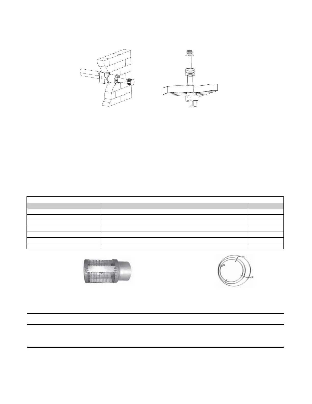
Figure 12. Horizontal and Vertical Venting Options
Horizontal Vent Terminal/Combustion Air Package Kit (Option CC6)
Field-supplied components required for installation of the horizontal vent kit are as follows:
• Vent and combustion air piping (refer to Table 5)
• Tapered vent pipe diameter reducers and/or increasers, as required
• Thimble (not required if wall is of non-combustible construction)
• Flashing
• Sheet metal screws, tape, and sealant, as required
Factory-supplied components for installation of the horizontal vent kit are listed in Table 6.
VENTING OPTIONS
Both venting options described below are shown in Figure 12.
Figure 13. Screened Exhaust Assembly and Inlet Guard
Option CC6 Installation Instructions
⚠ DANGER ⚠
To prevent combustion products from entering the occupied space, all vent terminals must be
positioned or located away from fresh air intakes, doors, and windows. Failure to comply could
result in severe personal injury or death and/or property damage.
1. Determine vent terminal location on outside wall:
a. Refer to Table 5 to ensure that location complies with vent length requirements.
b. For most applications, ensure that vent terminal is level with heater mounting height.
HORIZONTAL VENTING
(OPTION CC6)
VERTICAL VENTING
(OPTION CC2)
SCREENED EXHAUST ASSEMBLY INLET GUARD
 Loading...