42
I-SCE (09-18) PN207697R9
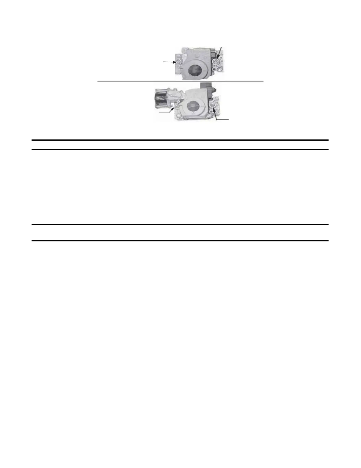
Figure 36. Combination Gas Valve Test Connections
NOTE: A manometer (fluid-filled gauge) with an inches water column scale is recommended.
a. With field-installed manual valve closed to prevent flow to gas valve, connect manometer to 1/8-inch FPT
INLET pressure tap (see Figure 36).
b. With field-installed manual valve closed, turn up thermostat to fire unit and to allow unit to go through one trial
for ignition.
c. Reset thermostat to shut OFF unit and observe manometer for 2 to 3 minutes for indication of gas pressure.
No pressure should be indicated on manometer. If manometer indicates gas pressure, field-installed manual
gas valve must be replaced or repaired before combination gas valve can be checked.
d. If manometer does not indicate gas pressure, slowly open field-installed manual gas valve. After manometer
indicates that gas pressure has reached equilibrium, close manual shutoff valve.
NOTE: Refer to Gas Piping and Pressures for operational pressure settings and instructions for
checking pressure settings.
e. Observe gas pressure on manometer. There should be no loss of gas pressure. If manometer indicates loss
of gas pressure, replace combination gas valve before placing heater in operation.
VENT/COMBUSTION AIR SYSTEM MAINTENANCE
Check vent/combustion air system at least once a year. Inspect all joints, seams, and terminal caps. Replace any
defective parts.
BURNER RACK MAINTENANCE
Remove, disassemble, clean, reassemble, and re-install burner rack as follows:
a. Remove burner rack
(1) Turn OFF gas and electric supply
(2) Remove control access side panel
(3) Disconnect ignition and flame sensor leads
(4) Mark and disconnect electric valve leads
(5) Uncouple union in gas supply
(6) Remove sheet metal screws in top corners of burner rack assembly
(7) Pull drawer-type burner rack out of furnace
Single-Stage
Valve
Two-Stage
Valve
1/8" INLET
Pressure Tap
1/8
Outlet
Pressure
Tap
1/8" INLET
Pressure Tap
1/8
Outlet
Pressure
Tap
"
"
OPERATING GAS VALVE MAINTENANCE—CONTINUED
 Loading...