27
I-SCE (09-18) PN207697R9
COMBUSTION AIR PROVING SWITCH
⚠ DANGER ⚠
Safe operation requires proper venting flow. Never bypass the combustion air proving switch or
attempt to operate the unit without the venter running and proper flow in the vent system. Hazardous
conditions could result.
The combustion air proving switch ensures that proper combustion airflow is available. The switch is a single-pole,
double-throw switch, which senses pressure caused by the flow of combustion air from the venter. The switch is
designed to close when a decreasing pressure is sensed in the outlet duct of the gas collection box.
At startup when the furnace is cold, the sensing pressure is at the most negative level, and as the furnace and
the flue system warm up, the sensing pressure becomes less negative. After the system has reached equilibrium
(approximately 20 minutes), the sensing pressure levels off. If a restriction or if excessive flue length or turns cause
the sensing pressure to become less than the switch setpoint, the pressure switch will function to shut off the main
burners. The main burners will remain off until the system has cooled and/or the flue system resistance is reduced.
Refer to Table 15 for approximate water column negative pressure readings and combustion air proving switch
setpoints for sea level operating conditions.
BLOWER FAN CONTROL
NOTE: To replace the blower fan control on units manufactured before NOV 2004, a replacement
kit is required. Order PN 209184.
CONTROL THERMOSTAT
A thermostat is not supplied with the furnace. Use either an optional or a field-provided low-voltage (24V) thermostat.
Install the thermostat according to the manufacturer’s instructions.
A low-voltage thermostat is equipped with a heat anticipator that levels out unit cycling for optimum temperature
control. Set the anticipator at 1.0 amps for standard controls. Refer to Table 14 for amp ratings of optional controls.
⚠ CAUTION ⚠
Control circuit amps should be within the anticipator amp rating of the thermostat used.
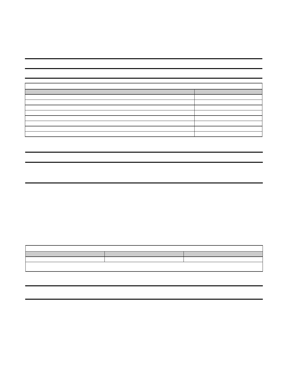
Table 14. Amp Ratings of 24-Volt Optional Controls
Control Ampere Rating (Amps)
Fan control 0.12
Time delay heater 0.14
RBM relay coil 0.12
Contactor coil 0.45
Spark ignition system 0.10
Maxitrol gas control system 0.51
Honeywell gas valve 0.50
White-Rodgers gas valve 0.60
Table 15. Combustion Air Proving Switch Settings at Sea Level Operating Conditions
Factory Setpoint Startup Cold Equilibrium
−0.58 IN WC (±0.05 IN WC) −1.0 IN WC −0.70 IN WC
NOTE: These settings apply to furnaces that are not equipped with air and gas modulation option AG39 or AG40. For pressure switch
settings for units equipped with option AG39 or AG40, refer to Table 18.
 Loading...