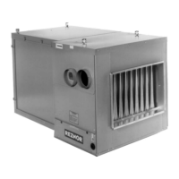
INSTALLATION AND STARTUP CHECKLISTS
PRE-STARTUP CHECKLIST
Installation Checks
Verify suspension/mounting methods and clearances (refer to Suspension, Mounting. and Clearances)
Verify that bolts removed from shipping clips have been returned to heater cabinet (refer to Uncrating/Unpacking)
Check duct connections (refer to Duct Connections)
Check venting (refer to Venting and Combustion Air) and ensure that flue discharge and combustion air openings
are free of obstructions
Ensure that electrical entrance and gas supply pipe openings are sealed
Ensure that all condensate drains are open (refer to Optional Condensation Drain for Duct Furnaces)
Electrical Checks
Ensure that electrical supply matches voltage rating of furnace (refer to rating plate)
Check all field wiring against wiring diagram and ensure that wire gauges are as required for electrical load
Ensure that fuses or circuit breakers are in place and are sized correctly
Gas Supply Checks
Check piping for leaks and proper gas line pressure and bleed trapped air from gas lines (refer to Gas Piping
and Pressures)
a. Turn OFF manual shutoff valve
b. Turn ON gas supply
c. Observe gas meter for movement or attach pressure gauge readable to 0.1 IN WC and, after turning gas on
for 10 seconds, turn OFF gas supply; no change in pressure should occur over 3-minute period
d. If step c indicates leak, locate leak by brushing soapy solution on all fittings; bubbles will appear at any leaks
e. Repair any leaks and repeat test
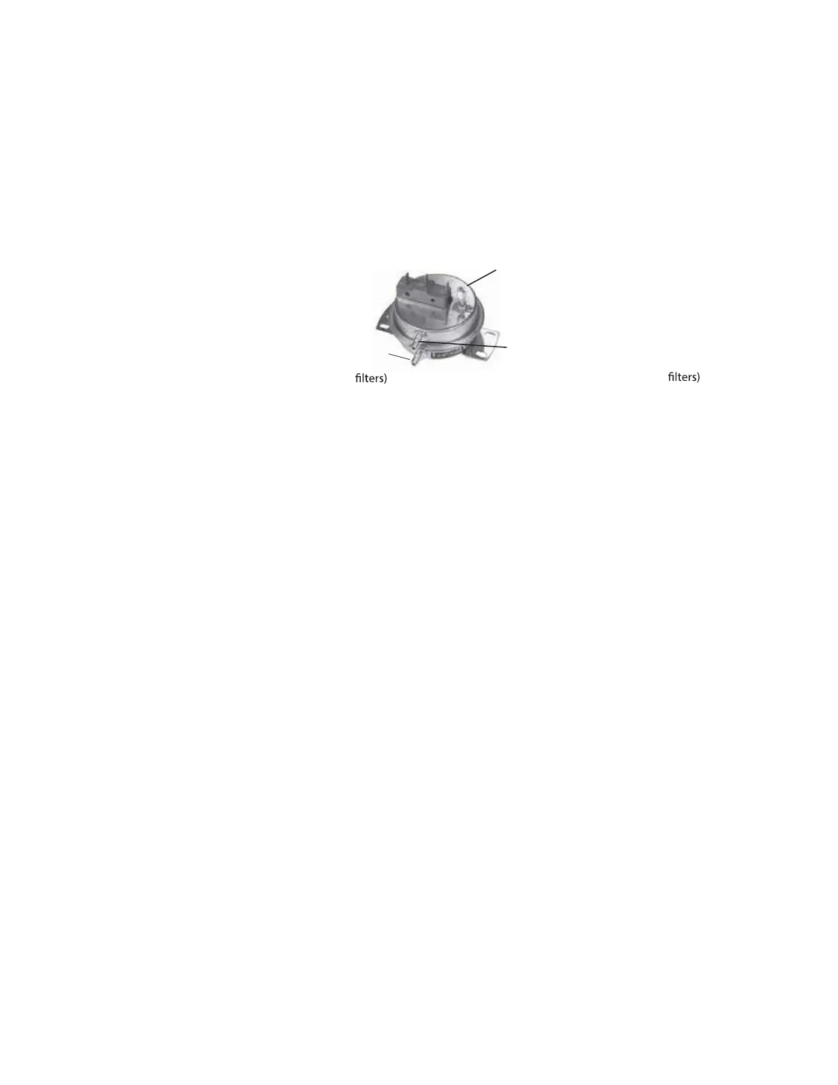
OPTIONAL DIRTY FILTER SWITCH
The optional dirty filter pressure switch is used to provide warning to the user by energizing an indicator light on
an optional remote console. The light indicates that the filters are in need of cleaning or changing. The adjustable,
single-pole/normally-open differential switch closes when an increase in pressure differential above the setpoint,
is sensed across the filter bank. The dirty filter switch is located in the furnace section. After the unit is started but
before continuous operation, the dirty filter switch must be set.
Instructions for Setting Dirty Filter Switch: With clean filters in place, blower doors closed, and the blower operating,
decrease the pressure setting by adjusting the setscrew on the switch (see Figure 35) clockwise until the indicator
light is energized or the setscrew is bottomed out. At that point, adjust the setscrew three full turns counterclockwise
or until the setscrew is top-ended. At that setpoint, the indicator light will be activated at approximately 50% filter
blockage.
Set screw (on front of switch)
must be manually adjusted after
the system is in operation.
Negative pressure connection is toward the
"back or bottom" of the switch (senses
blower side of
Positive pressure connection is
toward the "front or top" of the
switch (senses air inlet side of
Figure 35. Dirty Filter Switch
 Loading...