9
I-SCE (09-18) PN207697R9
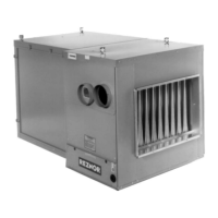
• Supply Air Duct/Furnace Horizontal Connection: The seal between the furnace and the duct must be mechanical
using U-type flanges on the top and bottom of the connecting duct to to ensure tight joints and an airtight fit. Refer
to Figure 7 and perform the following steps:
(1) Ensure that flanges on the furnace (heat exchanger) turn out as shown.
(2) Shape duct connection as shown: U-type on top and bottom and L-type on sides.
(3) Slide U-channels over furnace top and bottom flanges making connection.
(4) Form U-channels to seal sides (see DETAIL A) and drill and lock with sheet metal screws.
• Access Panels: Install removable access panels (see Figure 7) on both the upstream and downstream sides of
the furnace. The access panels must be accessible when the furnace is in service and should be a minimum of
6 × 10 inches (152 × 254 mm) in size so smoke or reflected light may be observed inside the casing to indicate
the presence of leaks in the heat exchanger. Ensure that the access panels are installed in such a manner so as
to prevent leakage.
• Return Air Duct/Furnace Connection: All return air ducts should be attached and sealed to the return air flanges
to provide airtight connections.
• Return Air Duct/Grill Size: Ensure that return air ducting or grills have a free area equal to the size of the return
duct connection.
Figure 7. Connecting Ductwork to Furnace
VENTING AND COMBUSTION AIR
⚠ WARNING ⚠
Do not use an existing venting system. This heater requires installation of the combustion air/vent
system ordered with the unit (either Option CC2 or Option CC6). Vent installation to be any listed
vent system manufacturer. Do not intermix different vent system parts from different manufacturers
in the same venting system.
All separated-combustion, power-vented units MUST BE equipped with both combustion air and exhaust piping to
the outdoors. The unique concentric adapter box designed for use with this heater allows for both combustion air
and exhaust piping with only one horizontal or vertical penetration hole in the building.
These instructions apply to installation and use of the concentric adapter and vent/combustion air kit (option CC2 or
CC6) designed for use with all Reznor separated-combustion products. The systems illustrated in this manual are
the only venting/combustion air systems approved for these separated-combustion units. Do not use this concentric
adapter box with any other products.
Installation should be done by a qualified agency in accordance with these instructions. The service agency installing
this separated-combustion system is responsible for the installation.
Hazards of Chlorine
⚠ WARNING ⚠
SC Series separated-combustion units are not designed or approved for use in atmospheres
containing flammable vapors or atmospheres highly-laden with chlorinated vapors.
 Loading...