18
I-SCE (09-18) PN207697R9
VENTING OPTIONS—CONTINUED
Vertical Vent Terminal/Combustion Air Package Kit (Option CC2)
Field-supplied components required for installation of the horizontal vent kit are as follows:
• Vent and combustion air piping (refer to Table 5)
• Tapered vent pipe diameter reducers and/or increasers, as required
• Thimble (not required if wall is of non-combustible construction)
• Flashing
• Sheet metal screws, tape, and sealant, as required
Factory-supplied components for installation of the vertical vent kit are listed in Table 8.
Table 8. Parts List for Vertical Vent Terminal/Combustion Air Package (Option CC2)
PN Description Qty
205896 Kit, Vertical Vent 1
205885 Assembly, Concentric Adapter Box (see Figure 10) 1
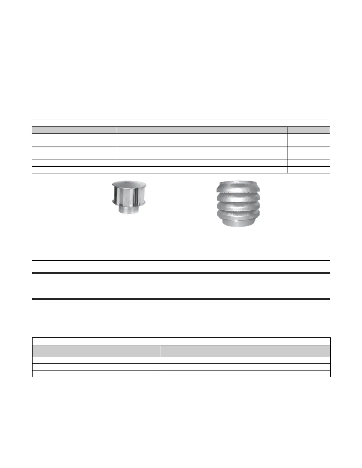
110052 Exhaust (Vent) Terminal (see Figure 16) 1
53330 Inlet, Combustion Air (see Figure 16) 1
207232 Bracket, Concentric Adapter Box (see Figure 14) 2
53335 Sealant, High Temperature (450°F), Silicone (Tube) 1
Figure 16. Exhaust (Vent) Terminal and Combustion Air Inlet
Option CC2 Installation Instructions
⚠ DANGER ⚠
To prevent combustion products from entering the occupied space, all vent terminals must be
positioned or located away from fresh air intakes, doors, and windows. Failure to comply could
result in severe personal injury or death and/or property damage.
1. Determine vent terminal location on outside wall:
a. If more than one vertical vent terminal is being installed, minimum spacing between vent center lines is
determined by minimum outdoor design temperature (coldest outdoor condition at installation site). Refer to
Table 9 to ensure that location complies with minimum outdoor design temperature requirements.
EXHAUST (VENT) TERMINAL
COMBUSTION AIR INLET
b. Select location away from fresh air intakes, allowing space for concentric adapter box inside. Vent terminal
must be located away from adjacent buildings as shown in Figure 17.
Table 9. Minimum Spacing Between Center Lines of Vertical Vent Pipes
Minimum Outdoor Design Temperature
Minimum Spacing Between Center Lines of Vertical Vent Pipes
(Inches (mm))
≥31°F (≥0°C) 36 (914)
−10 to 30°F (−23 to −1°C) 60 (1524)
< −10°F (< −23°C) 84 (2134)
 Loading...