24
I-SCE (09-18) PN207697R9
GAS PIPING AND PRESSURES—CONTINUED
Instructions to Check Valve Outlet (Manifold) Pressure
NOTE: A manometer (fluid-filled gauge) is recommended rather than a spring-type gauge due to
the difficulty of maintaining calibration of a spring-type gauge.
1. With the manual valve (on the combination valve) positioned to prevent flow to the main burners, connect a
manometer to the 1/8-inch pipe outlet pressure tap in the valve.
2. Open the valve and operate the heater. Measure the gas pressure to the manifold. To measure the low-stage
pressure on units equipped with a two-stage valve, disconnect the wire from the HI terminal on the valve. Be
sure to reconnect the wire.
3. Normally, adjustments to the factory-preset regulator should not be necessary. If adjustment is necessary, set
pressure to correct settings by turning the regulator screw IN (clockwise) to increase pressure. Turn the regulator
screw OUT (counterclockwise) to decrease pressure. Consult the valve manufacturer’s literature provided with
the furnace for more detailed information.
ELECTRICAL SUPPLY AND CONNECTIONS
• All electrical wiring must be completed in accordance with local, state, and national codes and regulations and
with the National Electric Code (ANSI/NFPA 70) or, in Canada, the Canadian Electric Code, Part 1 (CSA C.22.1).
• Check any local ordinances or gas company requirements that apply.
• Check the rating plate on the heater for the supply voltage and for current requirements. A separate line voltage
supply with fused disconnect switch should be run directly from the main electrical panel to the unit, making
connections in the junction box (see Figure 2).
• Seal all electrical entrance openings with field-supplied bushings.
• Refer to Table 12 for field-supplied wiring sizes—from disconnect to electrical box—for connection to the motor
contactor or starter.
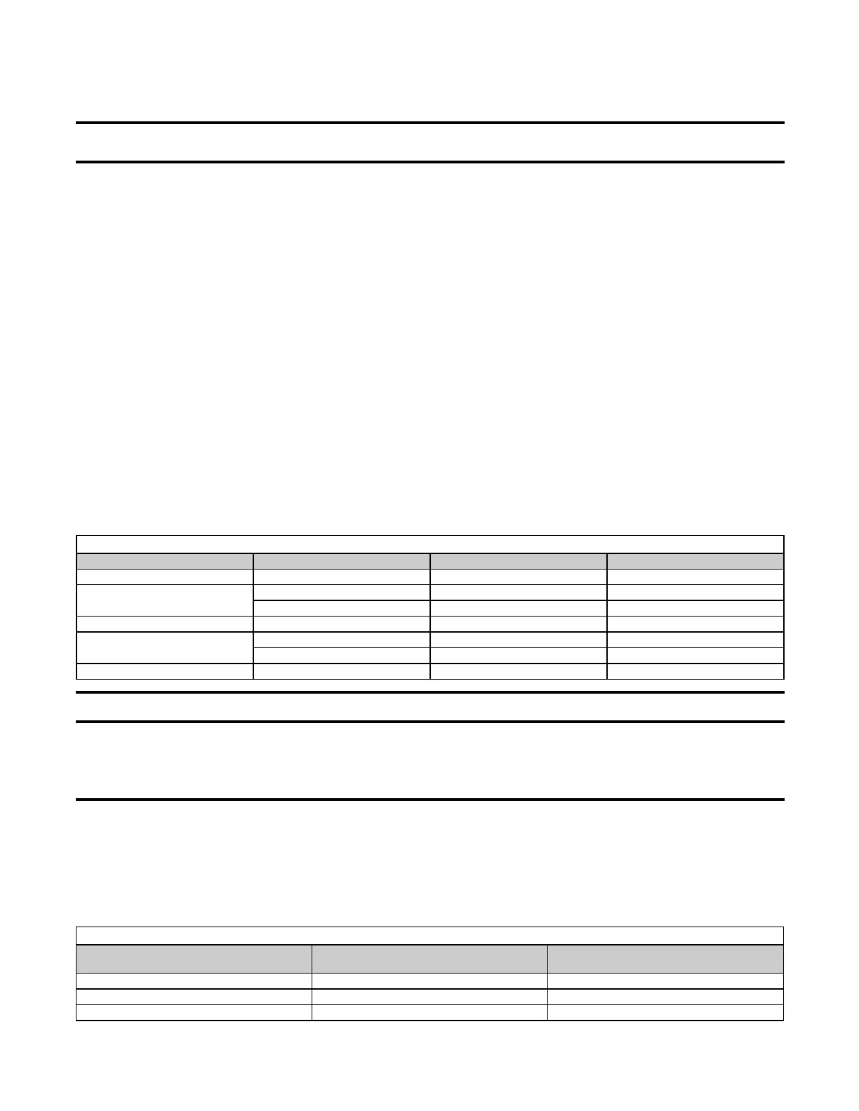
Table 12. Field-Supplied Wiring Sizes
Voltage/Phase Motor HP Wire Gauge BX Cable
120/1 1/4– 1/2 14 3/8
208–230/1
1 12 3/8
1–1-1/2 14 3/8
208–230/3 1/4–3 14 3/8
460/3
5 12 3/8
1/4–5 14 3/8
575/3 1/2–5 14 3/8
⚠ CAUTION ⚠
If any of the original wire as supplied with the appliance must be replaced, it must be replaced
with wiring material having a temperature rating of at least 105°C, except for the sensor lead and
the optional bypass damper combustion air safety circuit (option AG39 or AG40) wires, which must
be rated at 150°C.
• A disconnect switch is available as optional equipment or may be supplied locally. When installing the disconnect
switch, ensure that the conduit and switch housing are clear of all service panels. Allow at least 4 feet (1.2 M)
of service room between the disconnect switch and any removable service panels. When providing or replacing
fuses in a fusible disconnect switch, use dual-element time delay fuses sized at 1.25 × maximum total input amps.
• The heater is equipped with a low-voltage (24V) control circuit.
• Refer to Table 13 for field-supplied control wiring sizes.
Table 13. Field-Supplied Control Wiring Sizes
Distance from Unit to Control
(Feet (Meters))
Minimum Recommended Wire Gauge
(AWG)
Total Wire Length
(Feet (Meters))
75 (23) #18 150 (46)
125 (38) #16 250 (76)
175 (53) #14 350 (107)
 Loading...