31
I-SCE (09-18) PN207697R9
Optional Ductstat with Capillary Tubing (Option AG3): The unit-mounted ductstat shown in Figure 24 has an
adjustable range between 0°F and 100°F with a fixed differential of 3°F. Due to different cfm settings and outside
air temperatures, the average downstream outlet temperature may not match the ductstat setting exactly. After the
installation is complete, adjust the setpoint of the ductstat to achieve the desired average outlet air temperature.
Optional Ductstat with Electronic Remote Setpoint Module (Option AG15 or AG16): The field-installed sensing
probe is field-wired to the remote temperature selector shown in Figure 25, which has a temperature operating
range to 130°F. The remote modules and sensing probe are shipped separately for field-installation. Follow the
wiring diagram provided with the unit and the manufacturer’s instructions for wiring and installation. One module
is for selecting temperature, one module is a one-stage adder module, and the digital display module is optional.
⚠ CAUTION ⚠
Ensure that heat/cool selector switch on remote temperature selector is positioned to “Heat”.
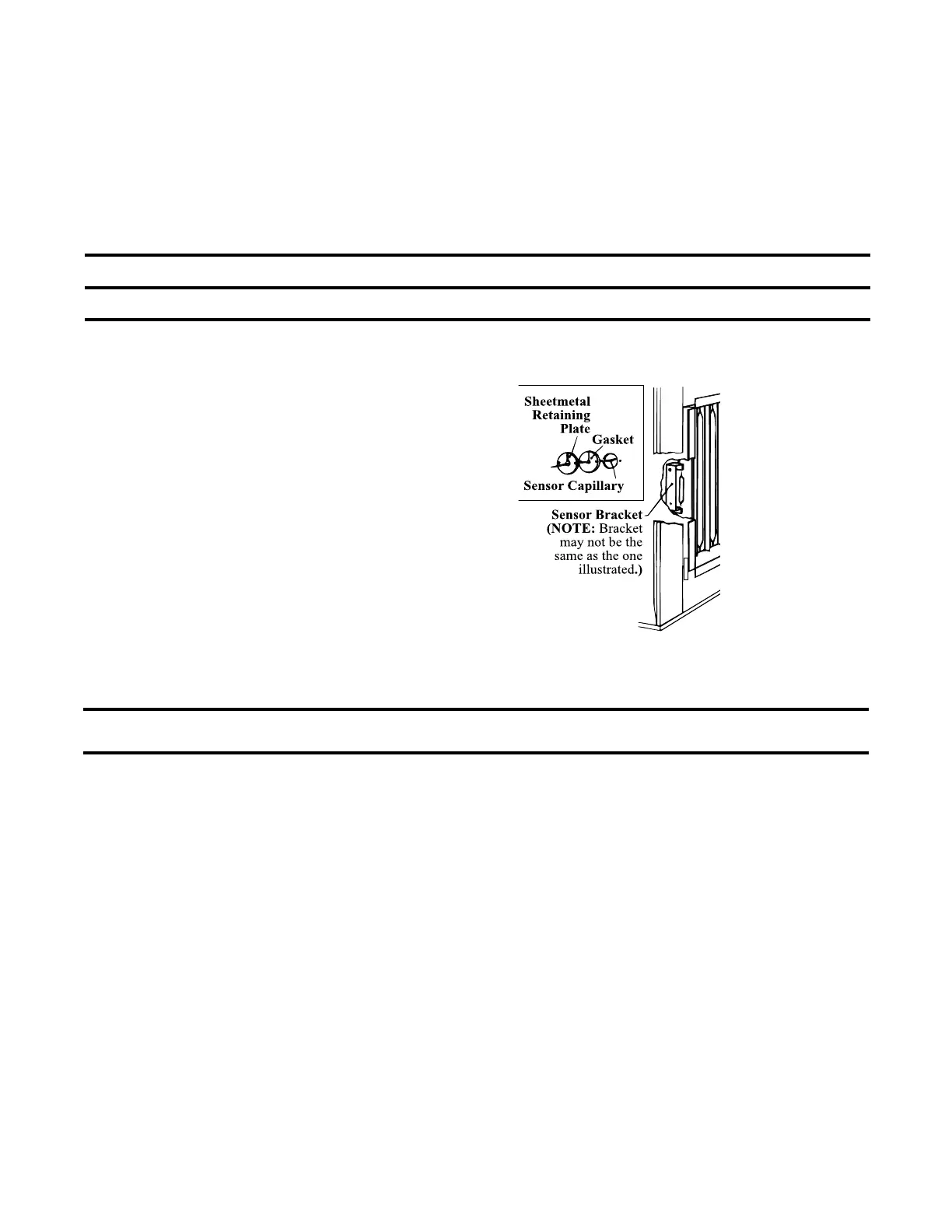
Figure 26 shows how to access the factory-installed sensor with either the unit-mounted ductstat (see Figure 24)
or the remote temperature selector (see Figure 25).
1. Remove access panel in ductwork
adjacent to control compartment
access panel.
2. Element is retained by spring clips.
3. Round gasket and metal retaining
plate provide airtight seal for capillary
and must be removed to remove the
element.
Figure 26. Accessing Duct Temperature Sensor
OPTIONAL ELECTRONIC MODULATION
NOTE: Sizes 350 and 400 with electronic modulation require a minimum natural gas supply
pressure of 6 IN WC.
Depending on heat requirements established by the thermistor sensor, the burner modulates up to 100% firing. The
thermistor is a resistor that is temperature sensitive in that as the surrounding temperature changes, the resistance
(ohms) changes through the thermistor. This change is monitored by the solid-state control center (amplifier), which
provides a varying DC current to the modulating valve to adjust the gas input.
Each modulating valve is basically a regulator with electrical means of raising and lowering discharge pressure.
When no DC current is fed to this device, it functions as a gas pressure regulator that supplies 3.5 IN WC pressure
to the main operating valve.
Refer to the wiring diagram supplied with the furnace for proper wiring connections for the electronic modulation system.
The type and capability of the electronic modulation system, depend on the option selected.
 Loading...