102 Rockwell Automation Publication 750-PM101B-EN-P - April 2022
Chapter 4 Troubleshooting
Hardware Service Manual The PowerFlex 750-Series AC Drive Hardware Service Manual, publication
750-TG100
, provides schematics and detailed instructions on part replacement
for PowerFlex 755T products.
The PowerFlex 755TS Products with TotalFORCE Control Hardware Service
Manual, publication 750-TG101
, provides schematics and detailed instructions
on part replacement for PowerFlex 755TS products.
Fault and Alarm Display
Codes
Event numbers for PowerFlex 750-Series faults and alarms are displayed in one
of three formats.
• Port 00 (Host Drive) displays the event number only. For example, code
21 ‘Clr Fault Queue’ is displayed as:
Fault Code 21.
• Ports 01 through 09 use the format PEEE, indicating port number (P) and
event number (EEE). For example, code 1 ‘Analog In Loss’ on an I/O
module installed in Port 4 is displayed as:
Fault Code 4001.
• Ports 10 through 14 use the format PPEEE, indicating port number (PP)
and event number (EEE). For example, code 37 ‘S OverTemp Alm’ on Port
14 is displayed as:
Fault Code 14037.
Common Symptoms and
Corrective Actions
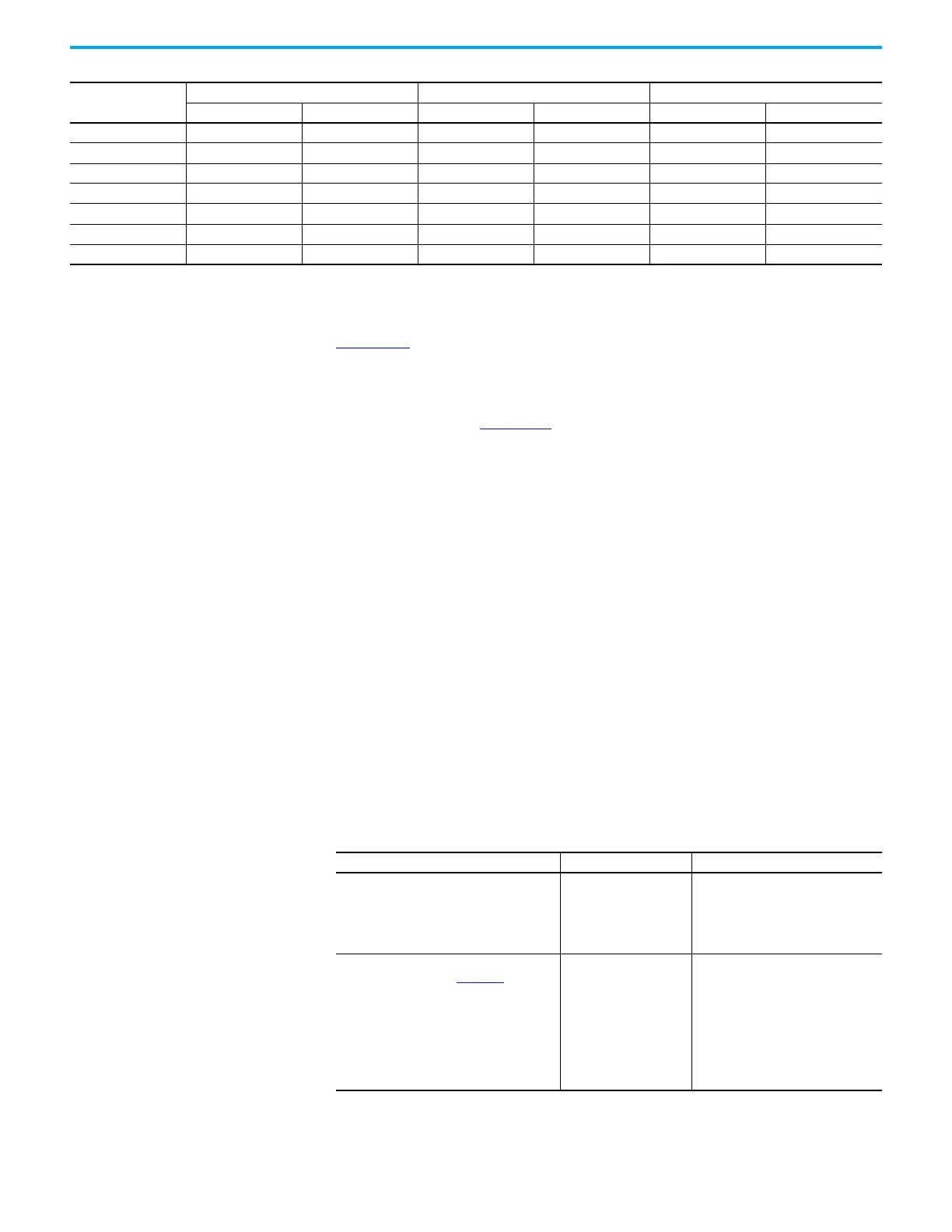
Fan Type
Frame 8 Common Bus Inverters Frame 9 Common Bus Inverters Frame 10…15 Common Bus Inverters
IP21, NEMA/UL Type 1 IP54, NEMA/UL Type 12 IP21, NEMA/UL Type 1 IP54, NEMA/UL Type 12 IP21, NEMA/UL Type 1 IP54, NEMA/UL Type 12
Control Pod Fan Dual Dual Dual Dual Dual Dual
Stirring Fan NoneNoneNoneNoneNoneNone
Heatsink Fan Present Present Present Present Present Present
Input Bay Fan NoneNoneNoneNoneNoneNone
Power Bay Roof Fan None Present None Present None Present
Wire Bay Fan Present (with option) Present (with option) Present (with option) Present (with option) Present (with option) Present (with option)
Control Bay Fan Present (with option) Present (with option) Present (with option) Present (with option) Present (with option) Present (with option)
Drive does not start from Start or Run inputs that are wired to the terminal block.
Cause(s) Indication Corrective Action
Drive is faulted Flashing red status light
Clear fault.
•Press Stop
•Cycle power
• ‘Clear Faults’ on the HIM Diagnostic
menu
Incorrect input wiring. See Installation
Instructions, publication 750-IN100
, for wiring
examples.
• 2-wire control requires Run, Run Forward,
Run Reverse, or Jog input
• 3-wire control requires Start and Stop
inputs
• Verify 24 Volt Common is connected to
Digital Input Common
None Wire inputs correctly.

 Loading...


