72 Rockwell Automation Publication 750-PM101B-EN-P - April 2022
Chapter 3 PowerFlex 755T Control Block Diagrams
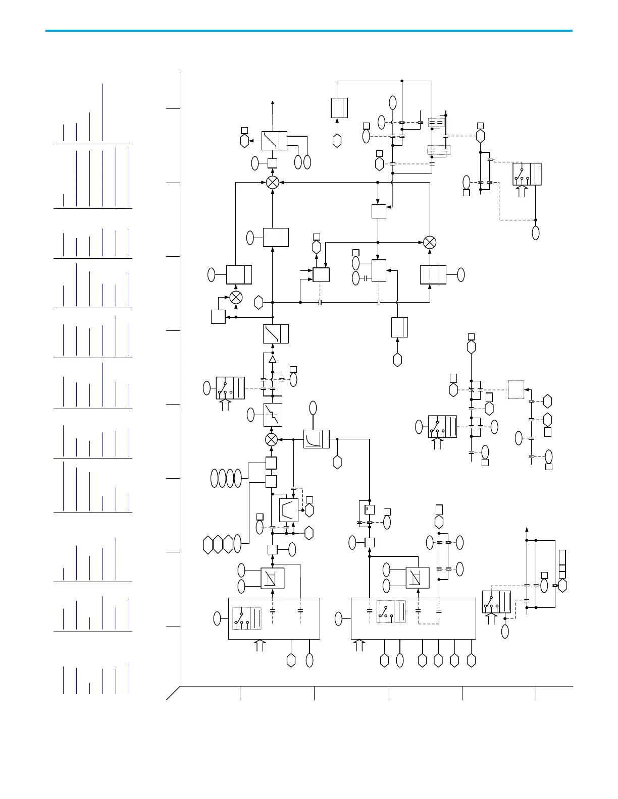
Figure 51 - Process Control 1
-
+
-
PID Setpoint
Default9:28
9:29 9:30
Scale
PID Ref
AnlgHi
PID Ref
AnlgLo
Option
Port:
Analog In
1823
1823
PID Fdbk Stpt
PID Ref Sel
9:25
PID Fdbk Sel
9:35
9:39 9:40
Scale
PID Fdbk
AnlgHi
PID Fdbk
AnlgLo
9:37
Trq Commanded
Torque Cur Fb
Analog Types
Analog Types
Float Types
Float Types
x
x
9:38
9:27
Output Current
Output Power
PID Fdbk Mult
PID Ref
Mult
9:26
PID Ref
Meter
Ramp
9:1
1
1
0
9:1
3
PID Fdbk
Meter
9:36
Error Deadband
9:9
PID
Deadband
-1
9:2 3
00
1
1
PID Control
(PID InvError)
PID Cfg
(Ramp Ref)
PID Error
Meter
9:12
Z
-1
200%
Limit
9:14 9:1 5
1
AntiWind
Up
9:3 1
Hold
+
+
D Gain
k
d
-S
1
2
3
4
5
6
BA
D
C
FHEG
I
+
E
-1
9:7
9:8
Limit
PID Upper Limit
PID Lower Limit
PID Output Limited
+
+
+
Analog Loss
9:42
9:439:14
1,2
3,4
≠0
≠0
355
10
PID FBLoss SpSel
PID FBLoss TqSelPID Output Sel
Motor Side Sts 2
(PID FB Loss)
PID Cfg
(Fdbk Sqrt)
PID Status
(PID Enabled)
9:3
0
1
0
Default
9:10
PID LPF
BW
9:6
PID Deriv
Time
9:4
PID Prop Gain
PID Status
(PID Hold)
PID Cfg (Anti
Windup)
PID Output Sel
9:21DI PID Hold
9:2
1
PID Control
(PID Hold)
9:20
Option
Port:
Digital In
DI PID Enable
9:20
DI PID Enable
0
354 16
354 18
9:3 0
PID Status
(PID Enabled)
PID
Stop
Mode
9:1
4
PID Cfg
(Stop Mode)
9:14
PID Output Sel
354
18
9:13
PID Output Meter
Motor Side Sts 1
(Stopping)
Motor Side Sts 1
(Stopping)
Motor Side Sts 1
(Running)
9:20
PID Control
(PID Enable)
2
0
9:5
PID Int Time
9:14
PID Output Sel
9:1
3
PID Cfg
(Preload Int)
9:3 0
PID Status
(PID Enabled)
1
0
Drive
InLimit
9:3 3
PID Status
(PID In Limit)
9:3 2
PID Status
(PID Reset)
9:22
PID Control
(PID Reset)
≠0
0.0
0.0
9:11
PID Preload
0
1
0
1
1
0,2,3,4
Accel Conditional
1
0
≠0
x
9:15
PID Output
Mult
0
Process Control 1 (Proc 1)
Parameter
Selection
PID Enable
Parameter
Selection
Parameter
Selection
Parameter
Selection
Option
Port:
Digital In
Option
Port:
Analog In
PID Hold
9:23
Option
Port:
Digital In
DI PID Invert
Parameter
Selection
Invert Error
9:22
DI PID Reset
Parameter
Selection
Option
Port:
Digital In
PID Reset
2073
8
3
4
Proc 2 [A2]
Proc 2 [D3, D6]
Proc 1 [H3]
Proc 1 [E5]
Conv
Hz
Per
Unit
1
Output Frequency
Conv
Hz
Per
Unit
1
Output Frequency
VRef Freq [I4]
1
1
1
Ref
NF1
LPass
Filter
Ref
NF2
1
Drive
InLimit
2 17-31
365
1
Proc 1 [C5]
Hold Request
Proc 1 [F2]
Hold Request
951
VRef Freq [I4]
Trq Ref Sel [H5]
948
950
949
Ref NF2 Freq
Ref NF2 Depth
Ref NF2 Width
Ref NF2 Gain
MOP Reference
MOP [G3]
MOP Reference
MOP [G3]
P Gain
k
p
I Gain
k
i
s
943
Ref NF1 Width
954
Ref NF1 Freq Act
956
Ref NF1 Depth Act
957
Ref NF1 Gain Act
From Anti-Sway [D2]
Overview VarCtrl PFC Vector Overview PRef Move Prof Ind 2 VelRefCAM Ld Obs Cur IPM MOP Logic
Metering DroopCtrl CurPwrLmt Freq Overview PRef2 Roll Psn VRef Vect Friction Comp Proc 1 22Series IO Digital Invert
PLL DBC CurrCtrl CBI Metering PReg Spindle Ref Move Trq RefCAM Proc 2 22Series IO Digital Motor I2T
PwrLoss VoltRefGen LscCtrlCfg Fdbk Psn PLL VRef Overview VReg Vect Trq Ref AntiSway 11-Series IO Digital High Speed Wizard
LscData VoltCtrl DriveDerating Homing Psn CAM VRef Sel Trq Overview Trq Filt Oil Well 1 22-Series IO Analog
CurRefGen DCBusObs PRef1 Prof Ind 1 VRef All Trq Ref Sel Cur IM SPM Oil Well 2 22-Series IO Analog Proc 1

 Loading...


