Rockwell Automation Publication 750-PM101B-EN-P - April 2022 91
Chapter 4 Troubleshooting
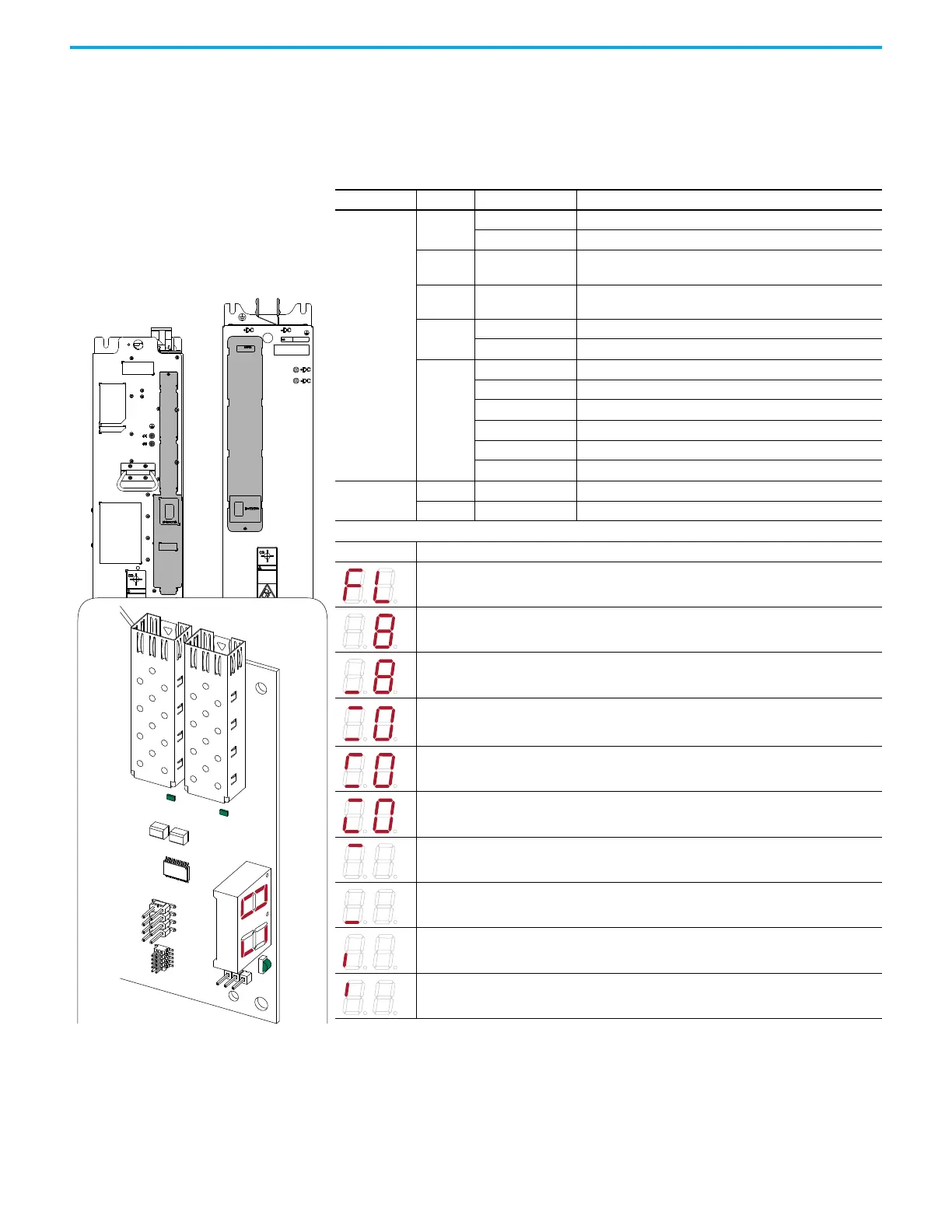
Power Layer Interface (PLI) Circuit Board Status Indicators
PowerFlex 755T power modules use status indicators and a 7-segment display
to report conditions. The power layer interface circuit board is located behind
the connections cover of the power module chassis.
Name Color State Description
DS3
Green
Flashing at 2 Hz Active mode in process.
Flashing at 0.5 Hz Update in process.
Green /
Yellow
Flashing Alternately Login mode in process.
Green /
Red
Flashing Alternately Erase in process.
Yellow
Flashing at 2 Hz Loopback fiber test mode is in process.
Flashing at 0.5 Hz Boot mode is in process.
Red
Blink 2 Count Clock fault
Blink 3 Count Firmware fault
Blink 4 Count FLEXBUS fault
Blink 5 Count PRGM fault
Blink 6 Count FPGA PRGM fault
Blink 7 Count SFLASH PRGM fault
DS5/DS6
Green Flashing Fiber connection is online.
Red Flashing Fiber connection is offline.
Lit Segment Description
Fiber loss
The PLI is not online.
The PLI is online but not initialized or logged in.
The PLI is initialized and logged in.
The right display indicates the module number (Lx/Mx). This display indicates that the module is
in a ready state.
The PLI is initialized, logged in, and PWM active.
The right display indicates the module number (Lx/Mx).
The PLI is initialized, logged in, and faulted.
The right display indicates the module number (Lx/Mx).
The PLI initialization is complete.
Fiber is online.
The PLI is faulted.
PWM is enabled.
Frame 8 and larger board orientation shown. Frame 7 is the opposite orientation.
DS5
7-Segment Display
DS6
DS3
Frame 8 and Larger
Power Module
Frame 7 Power Module
Connections Cover
Right
Display
Left
Display

 Loading...


