116 Rockwell Automation Publication DRIVES-AT005D-EN-P - May 2022
Appendix D Mixed Architecture Resources
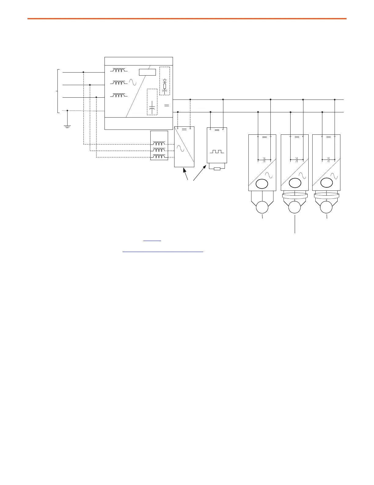
This diagram shows external regenerative methods with the PowerFlex 755TM Non-regenerative Supply.
Figure 19 - 600V AC PowerFlex 750-Series Mixed Architecture with PowerFlex 755TM Non-regenerative Supply
Diagram Notes:
• These DC bus voltage control methods are only applicable to 600V AC power systems. Do not use
PowerFlex 750-Series 600V AC frame 3...5 inverters on 690V AC power systems.
• AC and DC protection devices are required but not shown. See Appendix A
and the product technical
data for more information.
• Additional bus capacitance may be required. See DC Bus Capacitance Calculation Method on page 87
for more information.
• This diagram shows a solid ground AC source. High-resistance grounded AC sources can be used with
additional equipment.
• Regen Modules and Braking Modules aren’t available from Rockwell Automation. Contact third-party
suppliers for more information.
MMMM
CC
M
C
MMMM
CC
M
C
MMMM
CC
M
C
-
-
L1
L2
L3
PE
-
Bus Supply Converter
600V AC,
3-Phase AC
Power Source
Precharge
Cap
Bank
Bus
Cond
PowerFlex 755TM
Non-regenerative Supply
3-Phase
Reactor
Regen
Module
Or
Braking
Module
DBR
DC Bus
810V DC Nominal
1: PowerFlex 755TM CBI, Frames 8…15
2: PowerFlex 750, Frames 6, 7
3: PowerFlex 750, Frames 3…5
1
2
3
600/690v Class Inverters
DC Bus OV Trip = 1172V DC
600/690v Class Inverters
DC Bus OV Trip = 1162V DC
600v Class Inverters
DC Bus OV Trip = 1013V DC

 Loading...


