Rockwell Automation Publication DRIVES-AT005D-EN-P - May 2022 19
Chapter 2 Regenerative Bus Supply Configuration
General Considerations
• All system components must be selected for the same AC-line voltage.
• A low inductance type DC bus must be used. See DC Bus Connections on page 10
for details.
• The common DC bus system may require feeder and branch circuit protection and disconnect devices. Provide appropriate circuit
protection as required by national and local electrical safety codes and regulations.
• Depending on product family and frame size, AC and/or DC fuses may be provided internally or must be supplied external to the product.
See AC and DC Circuit Protection Devices on page 53
and the product technical data manuals for recommended fuse information.
• PowerFlex 755T AC drives and bus supplies must not be used on undersized or high-impedance AC supply systems. The supply system kVA
must be equal to or greater than the product-related kVA, and the system impedance must be less than 10%. Operation outside these limits
can cause instability and product shutdown. You must account for the kVA of all PowerFlex 755T drives and bus supplies on the distribution
system and the system impedance of upstream transformers.
- System Impedance = (PowerFlex 755T kVA ÷ Transformer kVA) x Transformer % Impedance
• The mixture of different frame size drives in this arrangement can cause high ripple current in the smaller frame drives. In this case, place
the larger power drives physically closer to the bus supply. This placement helps current sharing among the various drives on the bus.
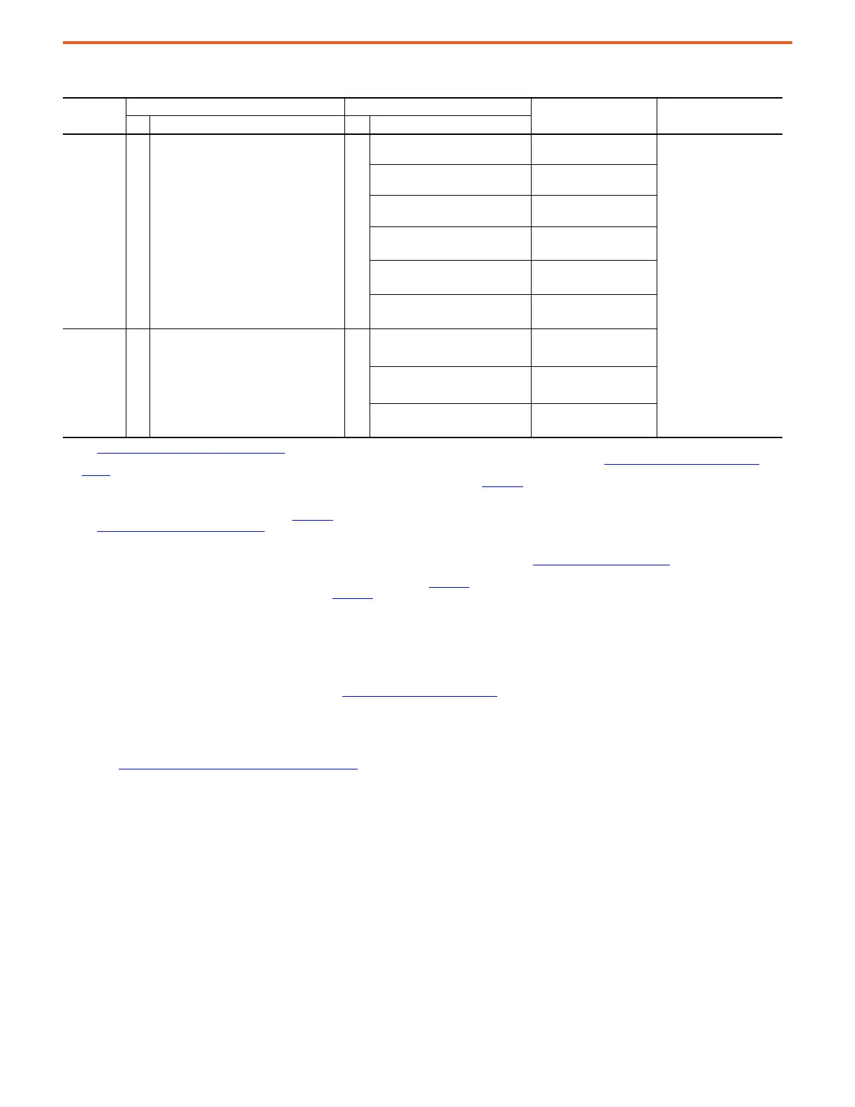
Table 1 - Compatibility Table
System
Voltage
Bus Supplies Inverter
Common Mode Core DC Bus ConditionerQty. Type Qty. Type
400/480V AC 1
PowerFlex 755TM Regenerative Bus Supply
(1)
(20J…): frames 7…15
(1) See PowerFlex 755TM System DC Bus Ratings on page 99 for guidance on PowerFlex 755TM system DC bus selection.
n
(2)
(2) The number of inverters that can be connected may be limited by the precharge capability of the PowerFlex 755TM regenerative bus supply. See DC Bus Capacitance Calculation Method on
page 87 for more information about DC bus capacitor calculations, system capacitance precharging requirements, and the maximum external DC bus capacitance that can be connected.
400/480V AC PowerFlex 750-Series:
frames 2…3
1321-M048
(3)
(3) For PowerFlex 750-Series frame 2…7 drives, common mode cores are required on inverter AC output only. See Appendix B and product technical data manuals for more information.
Solid Ground
(4)
:
-P50 option NOT required,
quantity of bus conditioners
determined by the catalog
number
High Resistance Grounded
(4)
:
-P50 power option is
required, quantity of bus
conditioners determined by
the catalog number
(4) The appropriate number of bus conditioner units internal to the PowerFlex 755TM Regenerative Bus Supply will be factory-installed depending on the frame size and -P50 option selection. Frame
6…7 regenerative bus supplies have built in bus conditioner circuits and can’t be specified with the -P50 power option. For shipboard ungrounded power sources, a marine bus conditioner, option
-P51, may be required (contact Rockwell Automation). See Appendix B
for more information about DC Bus Conditioner modules.
400/480V AC PowerFlex 750-Series:
frames 4…6
1321-M180
(3)
400/480V AC PowerFlex 750-Series:
frames 7
SK-Y1-CMCORE1
(3)
400/480V AC PowerFlex 755TM
Common Bus Inverter: frames 8…15
(5)
(5) See PowerFlex 755TM Control Pod Rule on page 101 for guidance on PowerFlex 755TM control pod selection.
Not required
(6)
(6) For PowerFlex 755TM common bus inverters, there are no provisions for AC output common mode cores; however, an optional reflective wave (dv/dt) filter is available. See catalog number
position 11 - filtering and CM cap configuration, EMI solutions.
Kinetix 5700 single-axis servo drives:
(2198-Sxxx-ERSx)
(7)
(7) To connect Kinetix 5700 servo drives to a common DC bus system, a capacitor module and other equipment is required. See Kinetix 5700 Servo Drives on page 102 for more information.
Not required
Kinetix 5700 dual-axis servo drives:
(2198-Dxxx-ERSx)
(7)
Not required
600/690V AC 1
PowerFlex 755TM Regenerative Bus Supply
(1)
(20J…): frames 7…15
n
(2)
600V AC PowerFlex 750-Series:
frames 3…5
(8)(9)
(8) When 600V AC frame 3...5 inverters are mixed with larger frame inverters on 600V AC common DC bus systems an external DC bus voltage control method may be required to limit the maximum
routine system DC bus voltage to less than the lowest inverter DC bus overvoltage trip level. See Appendix D for more information.
(9) 600V AC frame 3…5 inverters can’t be used on 690V AC systems. See Appendix D for more information.
Fr.3: 1321-M048
(3)
Fr.4…5: 1321-M180
(3)
600/690V AC PowerFlex 750-Series:
frames 6…7
Fr.6: 1321-M180
(3)
Fr.7: SK-Y1-CMCORE1
(3)
600/690V AC PowerFlex 755TM
Common Bus Inverter: frames 8…15
(5)
Not required
(6)

 Loading...


