12 Rockwell Automation Publication DRIVES-AT005D-EN-P - May 2022
Chapter 1 DC Bus Wiring Guidelines
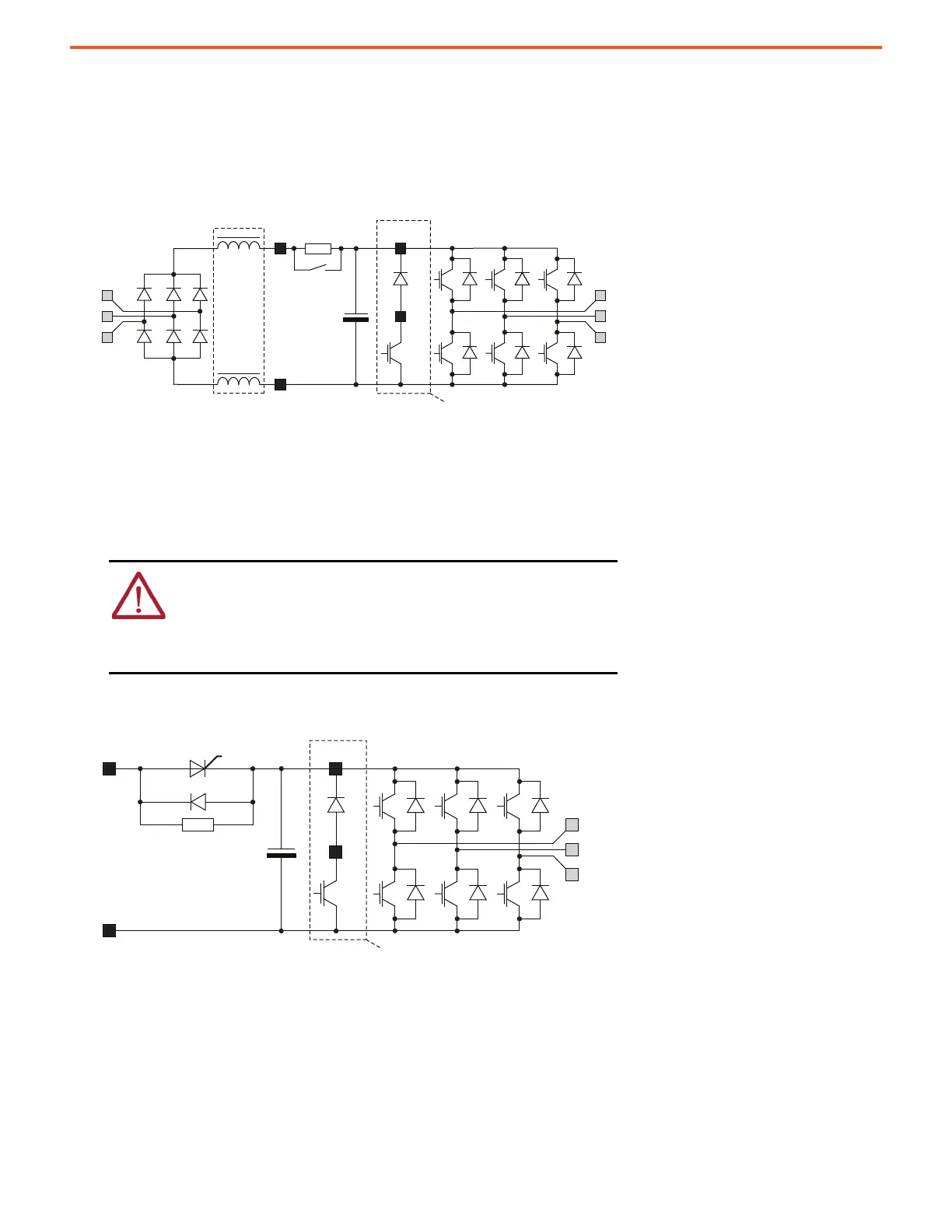
PowerFlex 750-Series Frame 1…4 AC Drives
For PowerFlex 750-Series frame 1…4 AC drives, the precharge hardware is on the power circuit board. It’s composed of a resistor in series with the
positive DC bus, between the DC link and the bus capacitors. The resistor has a relay contact that is connected in parallel, which closes to bypass
the precharge resistor when the bus precharge level is attained. The precharge function operates the same way for either AC or DC input power.
Figure 4 - AC and DC Input Schematic for PowerFlex 750-Series Frame 1…4 AC Drives (Input Type Cat. No. Position 5, Code 1)
PowerFlex 750-Series Frame 5…7 DC Input Common Bus Drives
The precharge has a resistor in series with the positive DC bus, ahead of the bus capacitors. A silicon-controlled rectifier (SCR) is connected in
parallel. Once the SCR is gated on, the precharge resistor is bypassed.
Figure 5 - DC Input Schematic for PowerFlex 750-Series Frame 5…7 DC Input Drives (Input Type Cat. No. Position 5, Code 4)
ATTENTION: PowerFlex 750-Series input type (position 5 of catalog
number) = 1 (frame 5 AC input with precharge, includes DC terminals) and,
input type = A (frame 6…7 AC input with precharge, no DC terminals) have
no method for the user to control the DC input precharge sequence.
Connection to a fully charged DC bus can result in severe drive and/or
equipment damage due to uncontrolled charging of the DC bus capacitors.
Optional for PowerFlex 700 Frame 4
Optional for Frames 6 and 7

 Loading...


