Rockwell Automation Publication DRIVES-AT005D-EN-P - May 2022 41
Chapter 4 Non-regenerative Bus Supply Configuration
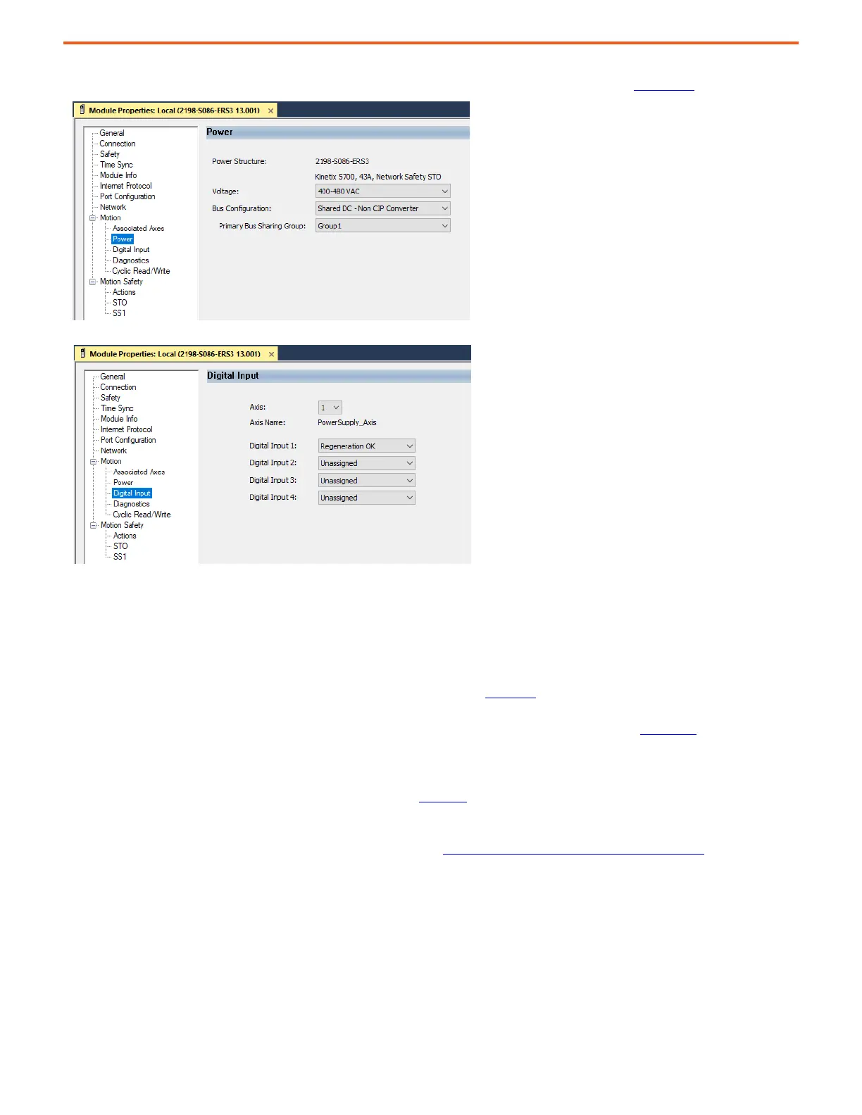
The following screen captures show the settings required for 'Shared DC - non-CIP Converter' bus configuration and 'Regeneration OK' digital input
within the Logix Designer application. For more details, see the Kinetix 5700 Servo Drives User Manual, publication 2198-UM002.
Paralleling PowerFlex 755TM Non-regenerative Modules
• The PowerFlex 755TM non-regenerative supply is available in two rating sizes: single density (1X) and dual density (2X). By paralleling
additional single- and/or dual-density modules, it’s possible to increase the rating of the overall non-regenerative bus supply.
• Parallel configurations are built-up from separate enclosures and 20-750-MN… single-density (1X) and dual-density (2X) roll-in modules. See
the PowerFlex 755TM IP00 Open Type Kits technical data manual, publication 750-TD101
, for more information.
• There are many possible combinations of paralleling single- and dual-density roll-in modules into a complete non-regenerative bus supply
converter. The ratings and specifications for single modules and various parallel configurations are shown in Appendix A
. Use these tables to
see the derated overall ratings. Use these tables to obtain the derated overall ratings for parallel combinations.
• Up to six single- and/or dual-density modules can be paralleled to configure a fully coordinated bus supply system for power ratings up to
4000 kW and 6000 Hp. Coordinated module operation requires that each parallel module is interconnected with the signal interconnection
harness. See PowerFlex 755TM IP00 Open Type Kits, publication 750-IN101
, for more information on parallel configurations.
• There are practical limitations to the current carrying capacity of the system bus bars and other components. Perform calculations for the
total bus supply rated DC current and make sure that the system requirements do not exceed the PowerFlex 755TM common DC bus system
bus bar rating (standard = 3000 A DC, option -P46 = 4700 A DC). See PowerFlex 755TM System DC Bus Ratings on page 99
for more
information about PowerFlex 755TM DC bus bar ratings. If the calculated total DC rated amps exceed these ratings, special design
considerations are required to make sure that the AC and DC bus bar systems are sized to handle the expected AC and DC currents. Back-to-
back or center-fed enclosure lineups may be used to satisfy these requirements. See the associated PowerFlex 755T technical data and
installation manuals for more information. Third-party enclosures with suitably rated AC and DC bus bars may also be employed to meet the
AC and DC current requirements of this example system.
• If you have an application that requires paralleling of more than six PowerFlex 755TM non-regenerative bus supply modules, contact
Rockwell Automation.

 Loading...


