22 Rockwell Automation Publication DRIVES-AT005D-EN-P - May 2022
Chapter 2 Regenerative Bus Supply Configuration
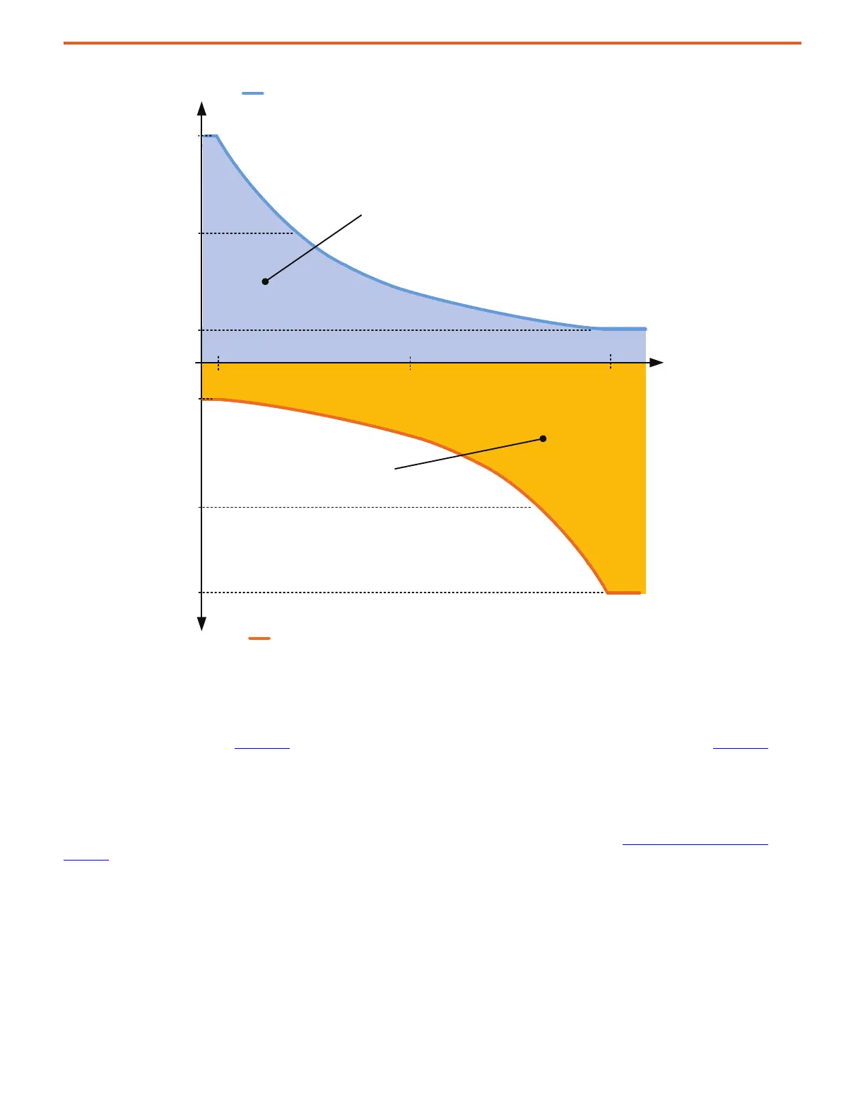
Figure 10 - Dynamic Bus Control, Non-linear Mode
For more information on Dynamic Bus Control and the parameters to configure this feature, see the PowerFlex Drives with TotalFORCE Control
Programming Manual, publication 750-PM100
, and the PowerFlex 750-Series Products with TotalFORCE Control Reference Manual, 750-RM100.
Kinetix 5700 Servo Drives
The Kinetix 5700 servo can be connected to 400/480V AC PowerFlex 755TM common DC bus systems. A capacitor module and other accessories
are required. For more information about applying the Kinetix 5700 to PowerFlex common DC bus systems, see Kinetix 5700 Servo Drives on
page 102.
When a Kinetix 5700 bus group is supplied by a PowerFlex 755TM regenerative bus supply, one of the Kinetix 5700 inverters in the bus group must
be configured in the Studio 5000 Logix Designer® application as 'Shared DC - Non-CIP Converter' and the bus supply ready status assigned to
Kinetix 5700 drive 'Regeneration OK' input.
The running status of the line side converter of the PowerFlex 755TM regenerative bus supply must be linked to a digital output on an I/O option
board and connected/interlocked with the 'Regeneration OK' input of the Kinetix 5700 drive. This connection doesn't signal that DC bus voltage is
present but rather when the PowerFlex 755TM regenerative bus supply is ready to supply power, allowing the Kinetix 5700 inverters to be enabled
and pull power from the bus.
(+) Motoring Power Limit
13:105 [Motor Power Lmt]
13:330 [DBC NomMtrPwrLm]
13:331 [DBC IdleMtrPwrLm]
13:333 [DBC IdleRgnPwrLm]
13:332 [DBC NomRgnPwrLm]
13:104 [Regen Power Lmt]
(-) Regeneration Power
Allowed Power Transfer
from AC Line
(Motoring)
13:62 [DBC V Thresh Lo]
13:64 [DBC V Thresh Nom]
13:63 [DBC V Thresh Hi]
DC Bus
Voltage
Allowed Power Transfer
to AC Line
(Regeneration)
0

 Loading...


