Rockwell Automation Publication DRIVES-AT005D-EN-P - May 2022 87
Appendix A Electrical Ratings, Recommended Protective Devices, and DC Bus Capacitance
Mersen HSJ Fuses
A test program was developed to confirm that Mersen HSJ (High-Speed J) fuses meet or exceed the requirements set forth by Rockwell Automation
for the fuses on the common DC bus for all Allen-Bradley architecture, component, and legacy drives.
The criteria for acceptance:
• 600V AC rectified, 810V DC average, fuses located at (+) and (-) leg. Short circuit test at 65 kA.
• Time constant minimum 3 milliseconds (maximum 15 milliseconds).
• No overload protection required.
• Let thru must be less than rating of the conductors.
This testing is listed in UL file E2137 Vol2 Sec 31 page 1 and in CSA report 1662646.
DC Bus Capacitance Calculation Method
All drives have a DC bus capacitance that is proportional to their power ratings. When used in a common DC bus configuration, these capacitors are
directly connected in parallel. This connection results in the DC bus ripple being shared proportional to the power rating of the drive. When the ratio
of the capacitance to the drive-rated current is consistent, it provides the best DC bus ripple sharing.
This ratio is expressed as µF/Amp ratio, which is the sum of all connected DC bus capacitance divided by the sum of the rated AC RMS output
current of each inverter connected to the DC bus. It’s important to evaluate every common DC bus drive system for any mismatch. When a
mismatch is found, the use of an external capacitor bank is required.
These calculations are based on the following bus supply converter configurations:
• Single PowerFlex 755TM Regenerative Bus Supply. See Chapter 2
.
• PowerFlex 755TM Non-regenerative Supply. See Chapter 4
.
• Two parallel PowerFlex 755TM Regenerative Bus Supplies. See Chapter 5
.
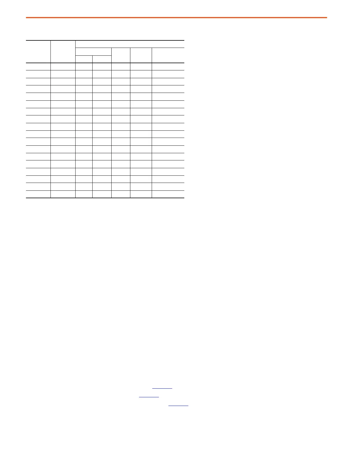
Table 23 - Cooper Bussmann 170M, DC Fuse Test for Rockwell Automation
Fuse Results
Circuit Parameters
Interrupting Amps
Volts DC
Time
Constant
Circuit
ConfigurationMin Max
170M6646 Acceptable — 69.8 kA 812 2 ms Configuration A
170M6646 Acceptable 10.2 kA — 812 1.66 ms Configuration A
170M6650 Acceptable — 69.6 kA 812 2 ms Configuration A
170M6650 Acceptable 21.1 kA — 812 1.2 ms Configuration A
170M7510 — 65 kA 810 2 ms
170M7510 20 kA — 810 2 ms
170M6792 — 65 kA 810 2 ms
170M6792 19 kA — 810 2 ms
170M6793 — 65 kA 810 2 ms
170M6793 23 kA — 810 2 ms
170M6794 — 65 kA 810 2 ms
170M6794 27.5 kA — 810 2 ms
170M6828 — 65 kA 810 2 ms
170M6828 37 kA — 810 2 ms
170M6934 Acceptable — 105.4 kA 810 1.8 ms Configuration A
170M6934 Acceptable 45.2 kA — 810 1.12 ms Configuration A
170M7560 — 100 kA 810 2 ms
170M7560 60 kA — 810 2 ms

 Loading...


