Rockwell Automation Publication DRIVES-AT005D-EN-P - May 2022 95
Appendix B
Power Component Accessories
This section provides information on power system components that may be required to complete the common DC bus configurations described in
this publication.
Bus Supply Capacitors
It’s important to evaluate every common DC bus drive system DC bus µF/A ratio as described in DC Bus Capacitance Calculation Method on page 87.
If insufficient DC bus capacitance is found, the use of an external capacitor bank is required.
Additional DC bus capacitor modules should be connected closest to the DC bus terminals of the largest connected inverter.
Capacitor modules can be custom designed or purchased from third party manufacturers. Make sure capacitor modules are designed for the
applicable system voltage and include components necessary to protect the capacitors. Follow the manufacturer recommendation for wire length
and capacitor bank mounting.
Optional factory installed DC bus capacitor modules are available for the PowerFlex 755TM non-regenerative bus supply. See the PowerFlex 755TM
non-regen supply rating tables in Appendix A
for more information.
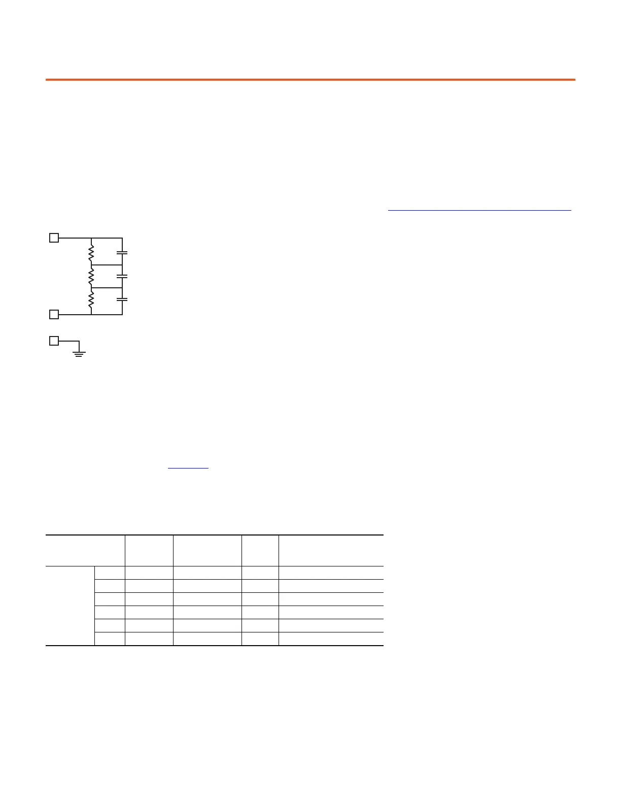
The following external capacitor bank modules are available from Rockwell Automation. The part numbers shown can be applied to common DC bus
systems up to 690V AC system voltage. The capacitor modules consist of capacitors in series with parallel combinations to achieve the stated total
capacitance. Internal voltage balancing discharge resistors are included. Other configurations are available. Contact Rockwell Automation for more
information.
Common Mode Core
The common mode core (CMC) is a passive ring-shaped filter that is comprised of ferrite material, which is designed to attenuate any high
frequency transient or disturbance on the wire or cable passing through it. This attenuation minimizes the risk of common mode interference with
other circuitry.
Part No.
(1)
(1) Contact Rockwell Automation for detailed ordering information.
Total
Capacitance
µF
Applicable System
AC Voltage Rating
Enclosure
Frame
Size
Dimensions HxWxD
mm (in)
30339-304-xx
-11/12 2000 400/480/600/690V Small 397x305x281 (15.63x12.00x11.06)
-09/10 4000 400/480/600/690V Small 397x305x281 (15.63x12.00x11.06)
-07/08 6000 400/480/600/690V Small 397x305x281 (15.63x12.00x11.06)
-05/06 8000 400/480/600/690V Large 692x305x281 (27.25x12x11.06)
-03/04 10000 400/480/600/690V Large 692x305x281 (27.25x12x11.06)
-01/02 12000 400/480/600/690V Large 692x305x281 (27.25x12x11.06)

 Loading...


