Rockwell Automation Publication DRIVES-AT005D-EN-P - May 2022 13
Chapter 1 DC Bus Wiring Guidelines
PowerFlex 755TM Frame 8…15 Common Bus Inverters
For PowerFlex 755TM frame 8…15 common bus inverters, the precharge function is implemented with a resistor and automatic bypass in both the
positive and negative DC bus between the DC input and the bus capacitors. When the DC bus precharge level has been reached, the motor-operated
circuit breaker (MCCB) closes, bypassing the resistor.
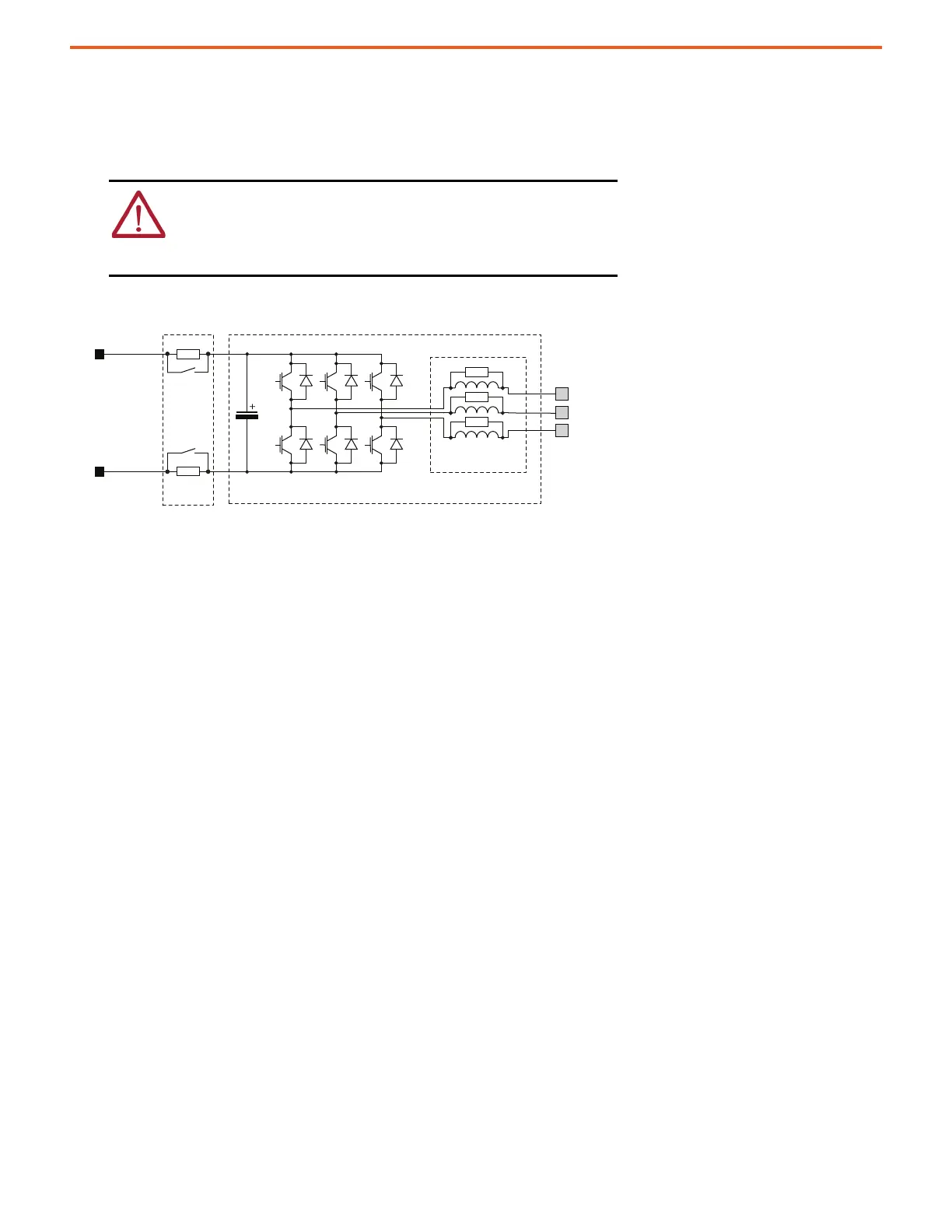
Figure 6 - DC Input Schematic for PowerFlex 755TM Frame 8…15 Common Bus Inverters (Input Type Cat. No. Position 5, Code D or E)
ATTENTION: PowerFlex 755TM common bus inverter input type (position 5
of catalog number) = E (common bus without precharge) have no method
for the user to control the DC input precharge sequence. Connection to a
fully charged DC bus can result in severe drive and/or equipment damage
due to uncontrolled charging of the DC bus capacitors.
1
2
3
U
V
W
DC+
DC-
1. Optional precharge – based on position 5 - input type catalog code selection.
D = common bus with DC precharge and E = common bus without DC precharge.
If input type = E (common bus without DC precharge), the DC fusing is contained within the DC bus connector
assembly.
2. Power module (roll-in).
3. Optional reflective wave filtering – based on position 11, filtering, and CM cap configuration selection.
This figure represents a PowerFlex 755TM frame 8 common bus inverter with an optional DC precharge and a reflective wave filter.

 Loading...


