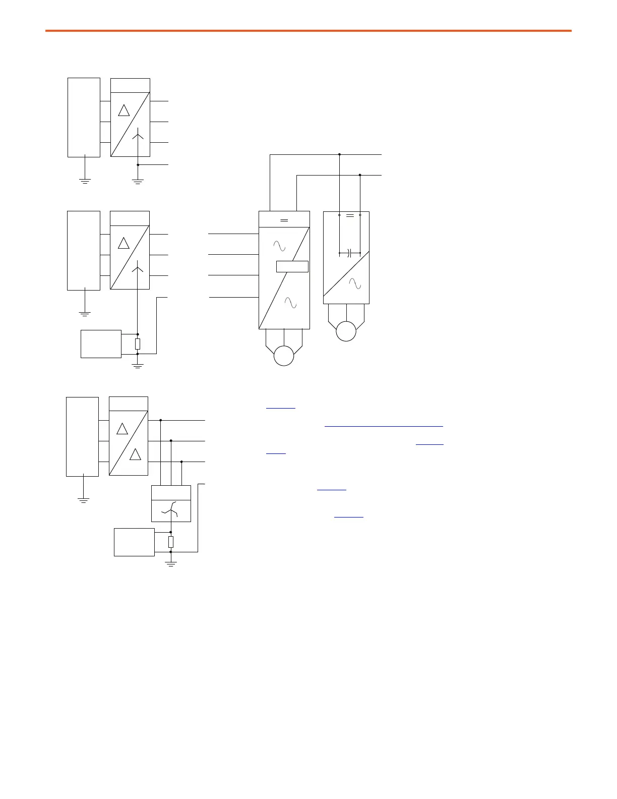
Diagram Notes:
• AC and DC circuit protection devices are required but not shown. See
Appendix A
for more information.
• The AC drive bus supply must be sized to power all inverters connected
to the DC bus. See See Sizing Shared Bus Supply AC Drive on page 33
for
more information.
• Additional DC bus conditioner units may be required. See Table 2 on
page 31.
• If inverter DC input disconnect devices are used, the inverter must have
a precharge circuit.
• High-resistance grounded power sources require a ground fault
indicator filter. See Appendix B
for more information.
• Delta secondary power sources require a Zig-Zag Transformer and
ground fault resistor (GFR) to convert the ungrounded power system to
resistance grounded. See Appendix B
for more information.
Solid Grounded AC Supply
3-Phase
AC Supply
Isolation
Transformer
3-Phase
AC Supply
Isolation
Transformer
Ground Fault
Detector and
Filter
3-Phase
AC Supply
Isolation
Transformer
Ground Fault
Detector and
Filter
Zig-Zag
Transformer
AC Drive
Bus Supply
AC Inverter
Precharge
Shared DC Bus Configuration

 Loading...


