USER'S AND
MAINTENANCE
MANUAL
01/31/2020
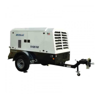
Air Compressor : D185T4F-DB
Copyright © 2014, ROTAIR S.P.A. - All rights reserved. This manual is intellectual property of ROTAIR S.P.A.
Its full or partial reproduction is forbidden under any form, on any support and by any means, without the
written authorization by ROTAIR S.P.A.
7.5 Hub and splined coupling (KTR Joint)
The engine and the compressor are interconnected by a hub and splined coupling which guarantees
concentricity between the engine flywheel and the compressor shaft. A large-size block joint with rubber
pieces inter-spaced transmits power in a smooth and silent way without splitting.
The engine and compressor, once assembled, are clamped to the frame with four flexible supports (silent-
blocks) which completely absorb the vibrations the machine generates. A fan is splined to the engine
shaft on the opposite side of the flywheel, generating large air displacement which cools the machine
fluids and parts.
7.6 Control panel
The control panel layout was specifically designed to have all of the controls within reach of a single
person. All the necessary instruments to control and monitor the unit are located on the control panel.
 Loading...