USER'S AND
MAINTENANCE
MANUAL
01/31/2020
Air Compressor : D185T4F-DB
Copyright © 2014, ROTAIR S.P.A. - All rights reserved. This manual is intellectual property of ROTAIR S.P.A.
Its full or partial reproduction is forbidden under any form, on any support and by any means, without the
written authorization by ROTAIR S.P.A.
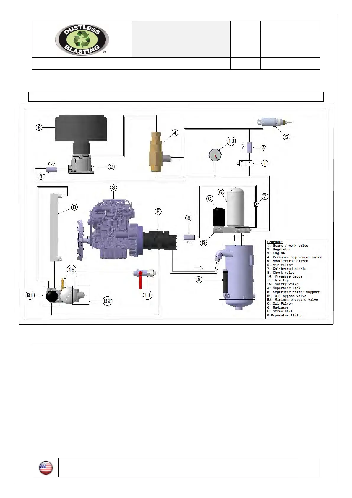
9 HYDRAULIC AND PNEUMATIC SYSTEMS
Figure 8.4-1 Hydraulic and pneumatic systems
9.1 Hydraulic lubrication system
The hydraulic lubrication system (Figure 8.4-1) of the compressor consists of:
- Oil mist separator tank (A)
- Oil mist separator filter (G)
- Minimum pressure valve (B2)
- Oil filter (C)
- Oil cooling radiator (D)
As you may notice, the lower portion of the oil mist separator tank (A) is used as an oil tank while the
minimum pressure valve located in the upper part (B) operates as a support of the oil mist separator filter (G).
When starting the machine, the oil under pressure located in the tank starts flowing through the tubing into
the oil filter (C) and from there to the cooling radiator (D).
The cooled filtered oil then reaches the compressor (F) and is distributed to the different parts (rotors,
bearings, etc.) which are then lubricated and cooled.
CAD-MADE DRAWING ANY MANUAL CHANGE IS FORBIDDEN
It is strictly forbidden to reproduce this drawing without authorization
 Loading...