USER'S AND
MAINTENANCE
MANUAL
01/31/2020
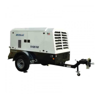
Air Compressor : D185T4F-DB
Copyright © 2014, ROTAIR S.P.A. - All rights reserved. This manual is intellectual property of ROTAIR S.P.A.
Its full or partial reproduction is forbidden under any form, on any support and by any means, without the
written authorization by ROTAIR S.P.A.
From the compressor (F), the oil is mixed with the compressed air from the check valve (8) and is sent to the
separator tank (A), where, through a forced centrifugal circuit, the first separation of the compressed air from
the oil occurs. The resulting compressed air leaves the separator tank through the oil mist separator filter (G),
which will provide a second and last separation of the oil from the compressed air.
Even though the separating filter (G) separates the oil from the air, it is worth pointing out that a limited quantity
of oil manages to penetrate inside the oil mist separator filter and deposits on the lower portion of the filter
itself.
The oil is sucked into the tubing where a calibrated nozzle (7) and a check-valve (8) will route it to the compressor
(F). The check valve (8) shall prevent the oil from returning to the oil mist separator filter (G) when the
machine is stopped.
Attention: The oil filter (C) is provided with a “by-pass” valve which allows the oil to circulate in case it is
clogged. In such case, the oil shall circulate regularly without being filtered.
WARNING: The filter therefore needs to be replaced at regular intervals, as specified in the
maintenance program.
9.2 Pneumatic system
The pneumatic system (Figure 8.4-1) includes:
- start/work valve (1)
- suction filter (6)
- suction adjustment valve (2)
- compressor (F)
- separator tank (A)
- oil mist separator filter (G)
- min. pressure and check valves integrated in the valve (B2)
- air valve (11)
- max. pressure valve (4)
The compressor suction air, after passing through the air filter (6), reaches the suction adjuster (2) and then
the compressor (F), which, after compressing it, directs it together with the injected oil into the separator tank
(A). Here, the oil is separated from the air. This process, as indicated above, is made by centrifugal force and
then by the use of the oil mist separator filter (G).
Once the air is separated from the oil, it is routed to the minimum pressure valve (B2) which opens only when
the pressure in the tank has reached the established value.
It is in any case a good practice not to use tools that, with their excessive consumption, may cause the
lowering of the pressure in the tank under 5-5.2 bar/72.5-75psi. Lengthened working conditions below 5
bar/72.5 psi may create insufficient separation of the oil from the air with subsequent excessive consumption
of lubricant. Furthermore, the minimum pressure valve (B2) acts as a check valve, thus preventing the return
of compressed air into the unit from piping or tools connected to the machinery.
WARNING: Pressure tank
 Loading...