5 x Start-up
67
FA ROTEX HeatPumpSolarUnit - Part 2 - 05/2009
Configure DIP switch
The DIP switches on the Outdoor Module (RRHQ) have already been preset in the factory. Before starting up the system for the
first time, the position of the switches on the Indoor and Outdoor Module must be checked against the pictures 5-2, 5-4 and 5-
6 and if necessary, configured on the basis of Tab. 5-1.
5.1.3 Checks before start-up
• Check all hydraulic connections for leakage.
• Check all refrigeration connections for leakage.
• Check all points on the "Checklist before start-up" (see chapter 5.2). Log the test results on the checklist.
Only if all points on the checklist can be answered with Yes may the ROTEX HeatPumpSolarUnit be temporarily started up.
5.1.4 Starting up ROTEX Solaris system (accessories)
When a ROTEX Solaris system is installed; start it up in accordance with the Installation and operating instructions that belong
to it.
5.1.5 Starting up a ROTEX HeatPumpSolarUnit
• Switch on mains switches of all components of the ROTEX HeatPumpSolarUnit.
• Start the system by pressing the key on the user interface.
• Wait for the start phase.
The number "88" is displayed for approx. 30 s during the start phase on the display of the user interface.
The system starts an automatic test run that lasts approx. 3 min.
During this test run, nothing particular is shown on the Display.
After a successful automatic test run, the system starts normal operation.
• Set time and weekday for control system (see Chapter 6.2.2 "Setting the control clock").
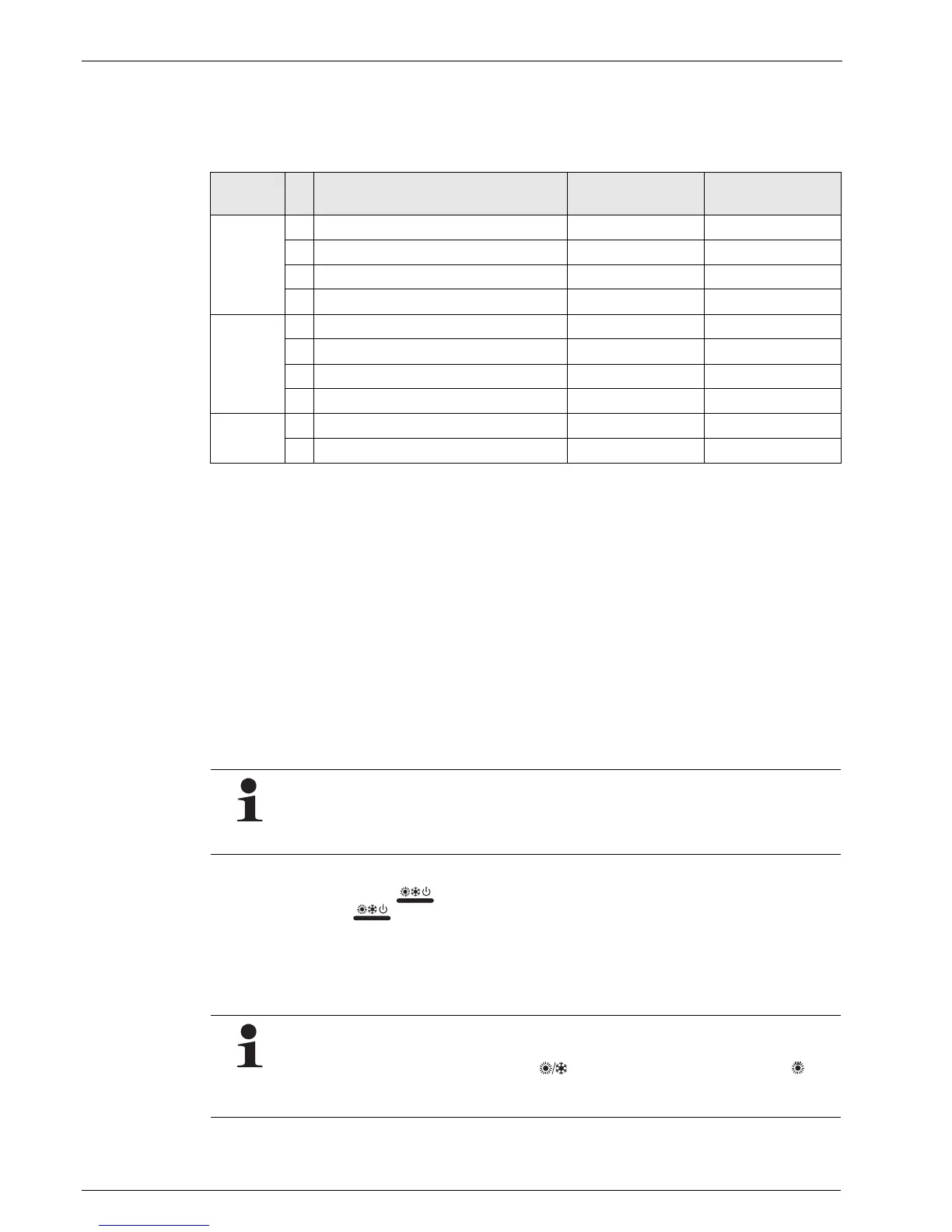
DIP switch Nam
e
Designation ON OFF
SW4
A Not applicable for fitter — S
B Not applicable for fitter — S
C Not applicable for fitter — S
D Not applicable for fitter — S
SS2
1 Not applicable for fitter — S
2 Hot water storage tank installed not installed
S)
3 Room thermostat / Pump operation installed / on not installed / off
S)
4 Priority circuit for the circulation pump
1)
Heating / cooling Hot water storage tank
)
DS1
1 Manual operation function On Off
S)
2 Operating mode in manual operation Cooling Heating
S)
Tab. 5-1 Configuration of DIP switches
1) Only valid if switch SS2-2 is set to "ON".
S) Standard factory setting
The power consumption required may be higher during the first 50 h (running in period) than the power con-
sumption stated on the type plate. This increased power consumption is caused by the compressor which
only achieves a stable power consumption after a running in period.
This state is not a material defect, but a typical feature of this component.
It is important that the water temperature does not fall below 10 °C during the test run. Otherwise the frost
protection switch could be activated and the test run would not be completed.
If the water temperature falls below 10 °C, the must be repeatedly pressed until the symbol is
displayed. This switches on the Backup Heater (BH) during the automatic test run and the water temperatures
is kept above 10 °C.
 Loading...