Figure 13: Trouble-free operation due to reversed direction of transmission of system
1
and
system
2
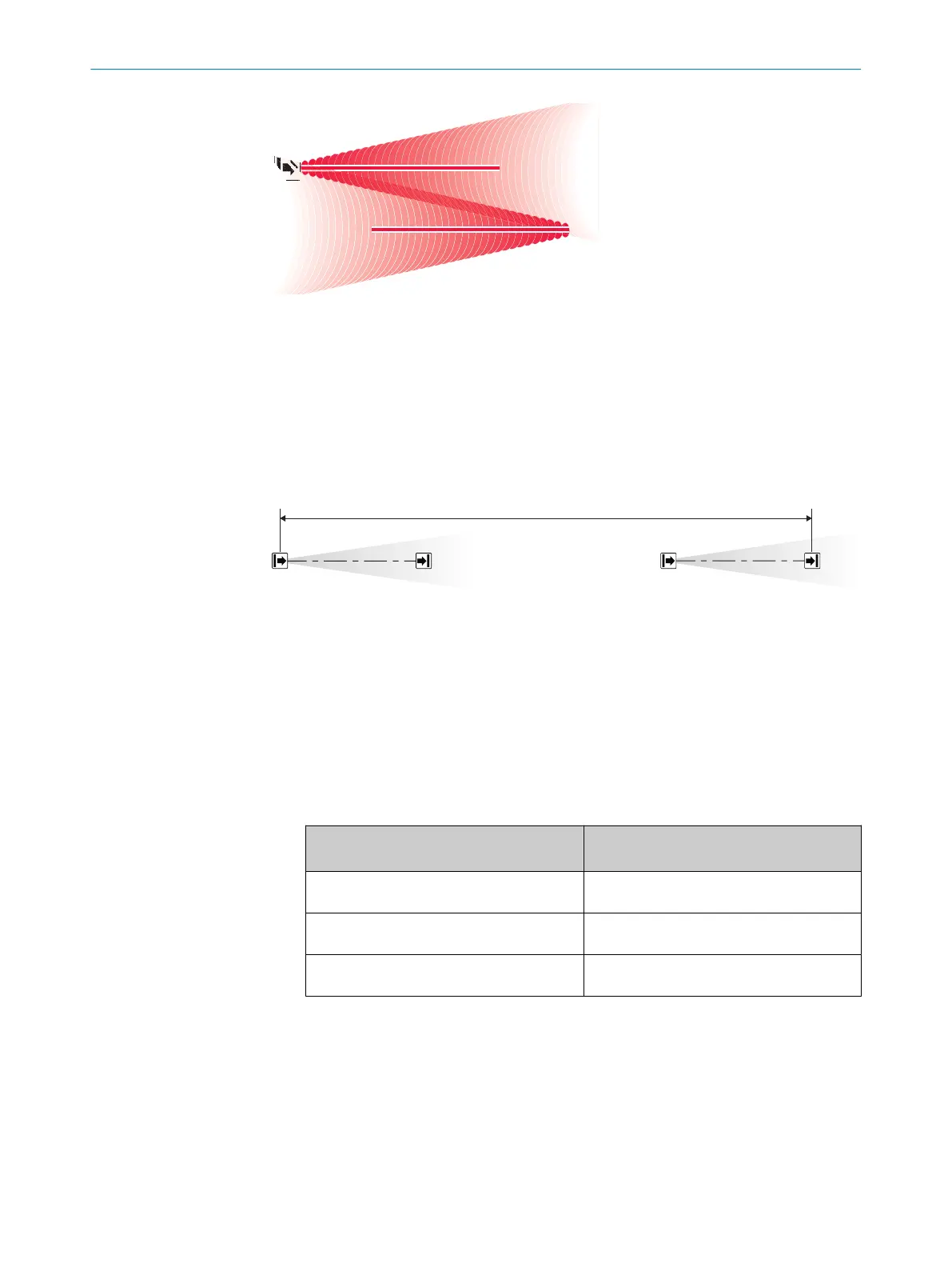
4.3.4.2 Maintaining sufficient distance
Overview
If s
ystems are installed in the same direction, sufficient distance between the two
systems must be maintained.
Determining sufficient distance
Figure 14: Trouble-free operation with sufficient distance
S
1
Sender of system 1
R
1
Receiver of system 1
S
2
Sender of system 2
R
2
Receiver of system 2
B Minimum distance between sender of the first system and receiver of the second system
w
ith the same direction of transmission
b
F
or systems with the same sender direction, consider the following minimum
distance B between sender S
1
and receiver R
2
:
Element R types:
2
Minimum distance B between sender S
1
and r
eceiver R
2
Receiver with low sensing sensing range
3.8m
10.5m
Receiver with medium sensing sensing
r
ange 6m
17m
Receiver with high sensing sensing range
12m
34m
4.3.4.3 Combining sufficient distance and reversed direction of transmission
Overview
To prevent mutual interference in the case of more than two neighboring systems, you
can combine the reversed direction of transmission and sufficient distance with each
other.
4 PROJECT PLANNING
22
O P E R A T I N G I N S T R U C T I O N S | deTec4 Core Vibes 8024467/1GWF/2022-11-11 | SICK
Subject to change without notice

 Loading...


