•
"S
ender and receiver alignment", page 41
•
"Alignment with the QuickFix bracket", page 43
5.3.1 Mounting the QuickFix bracket
Overview
2 Q
uickFix brackets are used to mount the sender and receiver.
The QuickFix bracket consists of 2 parts, which are pushed into each other. The two
individual parts are connected with an M5 screw and the housing (sender or receiver) is
clamped with form-fit clamping.
The two mounting surfaces for the brackets of the sender or receiver must be parallel
and lie in the same plane.
Important information
NOTE
T
he following should be considered when mounting the QuickFix bracket:
•
Select the appropriate length of the M5 screw to prevent any risk of injury from an
overrun.
•
When selecting the screw length, observe the wall thickness and the depth of the
countersunk screw of the QuickFix bracket, see figure 29, page 59
NOTE
T
he QuickFix bracket has cable routing. Depending on the installation, the cable routing
can make mounting easier.
Mount QuickFix bracket on a machine or profile frame
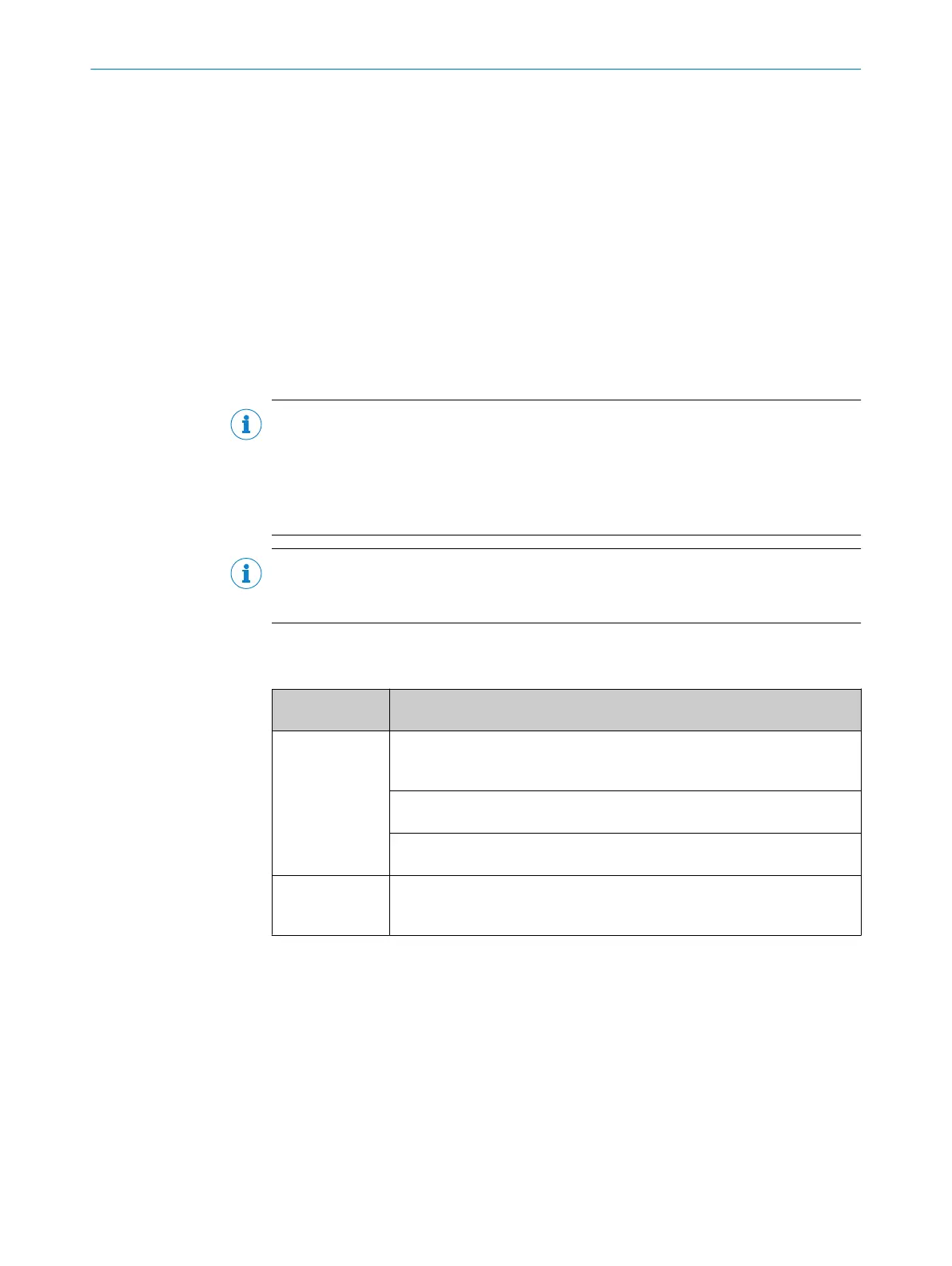
T
able 4: Side and rear mounting with the QuickFix bracket
Mounting
me
thod
Description
On the side Fasten the M5 screw to the machine or profile frame through the QuickFix
br
acket. A screw nut or threaded hole is required on the machine or profile
frame (1).
Fasten the M5 screw to the QuickFix bracket through the machine or profile
fr
ame. A screw nut is required for each QuickFix bracket (2).
Fasten the M5 screw to the profile frame through the QuickFix bracket. A
slidin
g nut is required on the profile frame (3).
On the back Fasten the M5 screw to the machine or profile frame through the QuickFix
br
acket. A screw nut or threaded hole is required on the machine or profile
frame (4).
Tightening torque: 5Nm…6Nm
5 MOUNTING
36
O P E R A T I N G I N S T R U C T I O N S | deTec4 Core Vibes 8024467/1GWF/2022-11-11 | SICK
Subject to change without notice

 Loading...


