Parameters/address space
5.7 Parameters of the digital on-board I/O
CPU 1512C-1 PN (6ES7512-1CK00-0AB0)
Manual, 09/2016, A5E35306440-AB
113
Parameters of the digital on-board I/O
Parameters of the digital on-board I/O in standard mode
You specify the properties of the digital on-board I/O during the parameter assignment with
STEP 7 (TIA Portal). The tables below list the parameters that can be set for inputs and
outputs, respectively.
When parameters are assigned in the user program, they are transferred to the digital on-
board I/O via data records with the WRREC instruction, see section Parameter assignment
and structure of the parameter data records of the digital on-board I/O (Page 158).
The use of a digital input by a technology channel
When a digital input is in use by a technology channel (HSC, PTO or PWM) the
corresponding digital input channel remains fully usable without any restriction.
Use of a digital output by a technology channel
When a digital output is in use by a technology channel (HSC, PTO or PWM) the following
restrictions apply to the use of the corresponding digital output channel:
● Output values for the digital output channel are not effective. The output values are
specified by the technology channel.
● The CPU STOP behavior configured for the digital output channel is not effective. The
reaction of the output to CPU Stop is specified by the technology channel.
● With activated value status (Quality Information) for the DI16/DQ16 submodule, the QI-bit
for the digital output channel shows the value 0 (= Status "Bad").
● The current state of the digital output is not returned to the process image output. In the
PTO operating mode, you can only observe the switching operations of the assigned
digital outputs directly at the output. In the PWM operating mode and with high-speed
counters (HSC), you can observe the current state additionally via the feedback interface.
Note, however, that high frequencies may no longer be observed under certain
circumstances due to an excessively low sampling rate.
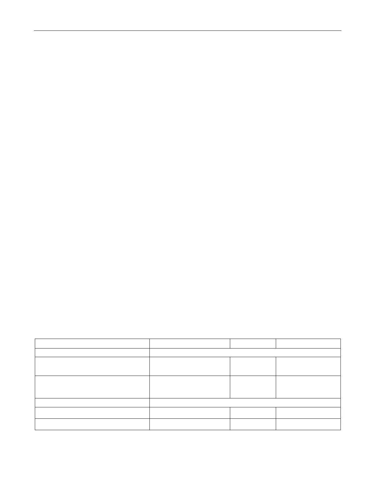
Configurable parameters and default settings for inputs
Table 5- 10 Configurable parameters for inputs
• No
supply voltage L+
Yes/No No Yes
None, 0.05 ms, 0.1 ms,
0.4 ms, 1.6 ms, 3.2 ms,
3.2 ms Yes
• Rising edge
Yes/No No Yes
• Falling edge
Yes/No No Yes
1)
All parameters can be set channel-selective

 Loading...


