Product overview
2.4 Operator controls and display elements
CPU 1512C-1 PN (6ES7512-1CK00-0AB0)
Manual, 09/2016, A5E35306440-AB
33
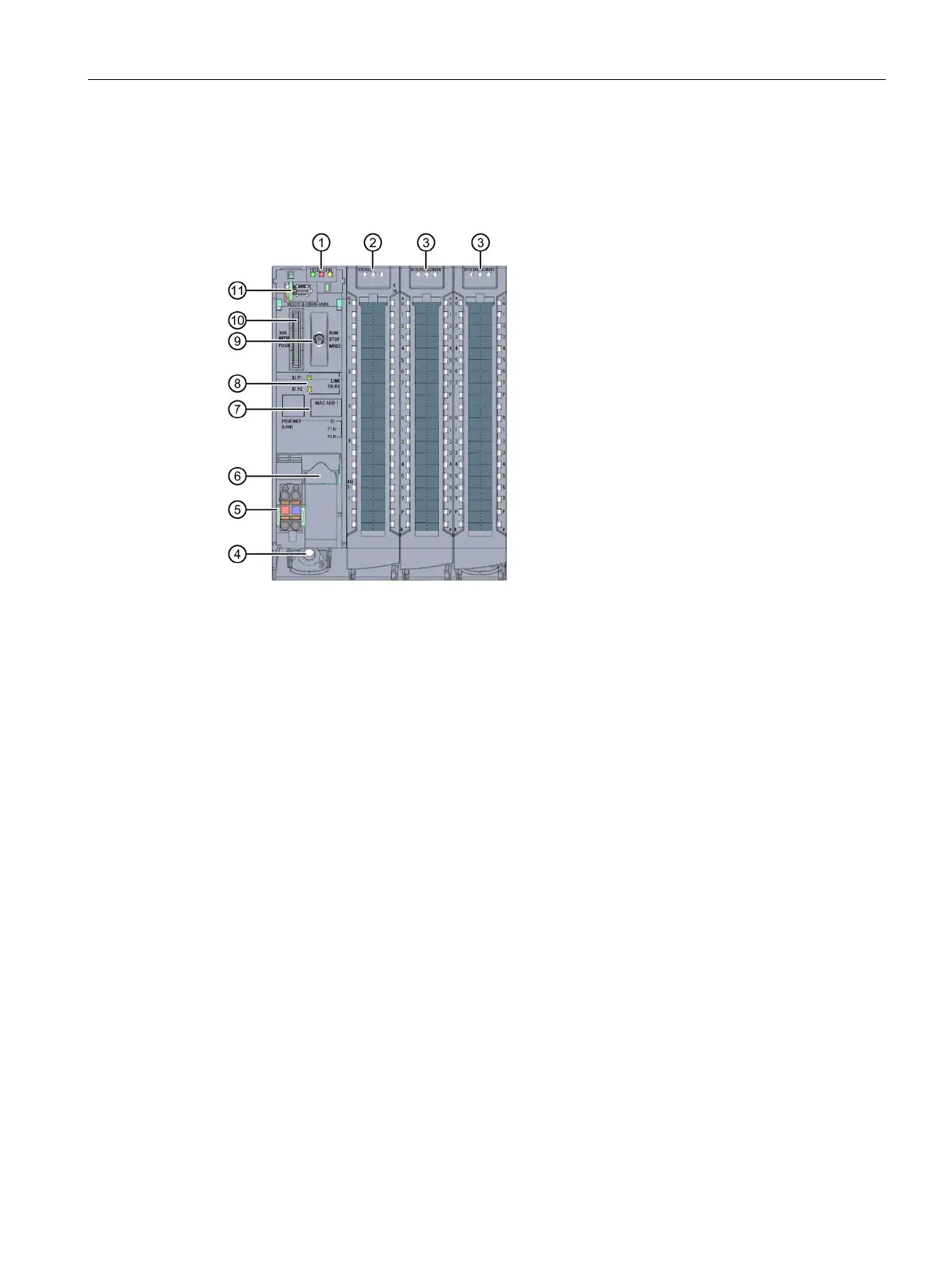
Front view without front panel on the CPU
The following figure shows the operator control and connection elements of the
CPU 1512C-1 PN with the front cover of the CPU open.
LEDs for the current operating mode and diagnostics status of the CPU
Status and error displays RUN/ERROR of the analog on-board I/O
Status and error displays RUN/ERROR of the digital on-board I/O
Connection for supply voltage
PROFINET interface (X1) with 2 ports (X1 P1 and X1 P2)
LEDs for the 2 ports (X1 P1 and X1 P2) of the PROFINET interface X1
Slot for the SIMATIC memory card
Figure 2-6 View of the CPU 1512C-1 PN without front panel on the CPU (front)

 Loading...


