Home
Siemens
Controller
CPU 1518-4 PN/DP ODK
Siemens CPU 1518-4 PN/DP ODK User Manual
4
of 1
of 1 rating
188 pages
Give review
Manual
Specs
To Next Page
To Next Page
To Previous Page
To Previous Page
Loading...
Interrupts
/diagnost
ics al
arms
6.1
Stat
us and err
or display
s
CPU 1512C
-
1 PN (6ES7512
-
1CK00
-
0AB0)
118
Manual
,
09/2016
,
A5E35306440
-
AB
6.1.2
Status and
error di
splays
of the anal
og on
-
board I
/O
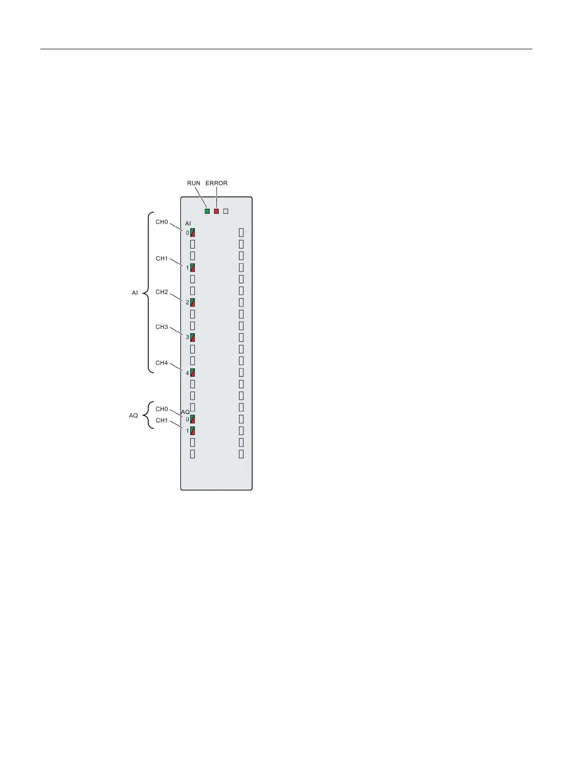
LED disp
lays
The figure
below sh
ows the
LED disp
lays (s
tatus and e
rror displ
ays) of the
ana
lo
g on
-
board
I/O.
Figure
6-2
LED displa
ys
117
119
Table of Contents
Default Chapter
4
Preface
4
Table of Contents
6
1 Documentation Guide
9
2 Product Overview
13
New Functions in Firmware Version V2.0
13
Applications of the S7-1500 Cpus
16
Properties
21
Properties of the CPU Part
22
Properties of the Analog On-Board I/O
27
Properties of the Digital On-Board I/O
29
Operator Controls and Display Elements
31
Front View with Closed Front Panels
31
Front View Without Front Panel on the CPU
33
Rear View
34
Mode Selector
34
3 Technology Functions
35
High-Speed Counters
35
Functions
36
Counting
36
Measuring
37
Position Detection for Motion Control
38
Additional Functions
39
Configuring the High-Speed Counters
40
General
40
Assignment of the Control Interface of the High-Speed Counters
40
Assignment of the Feedback Interface of the High-Speed Counters
42
Pulse Generators
44
Operating Modes
44
Operating Mode: Pulse-Width Modulation (PWM)
44
Operating Mode: Frequency Output
51
Operating Mode: PTO
55
Functions
60
Function: High-Speed Output
60
Function: Direct Control of the Pulse Output (DQA)
61
Configuring the PWM and Frequency Output Modes
62
Assignment of the Control Interface
62
Handling the SLOT Parameter (Control Interface)
64
Assignment of the Feedback Interface
67
4 Wiring
69
Supply Voltage
69
PROFINET Interfaces
70
Terminal and Block Diagrams
71
Block Diagram of the CPU Part
71
Terminal and Block Diagram of the Analog On-Board I/O
72
Terminal and Block Diagram of the Digital On-Board I/O
81
Addresses of the High-Speed Counters
93
Addresses of the Pulse Generators in the Pulse Width Modulation (PWM) and Frequency Output Modes
96
Addresses of Pulse Generators in the PTO Mode
97
Interconnection Overview of the Inputs
98
Interconnection Overview of Outputs
100
5 Parameters/Address Space
103
Address Space of the Analog On-Board I/O
103
Address Space of the Digital On-Board I/O
105
Address Space of the Pulse Generators
108
Measurement Types and Measuring Ranges of the Analog On-Board I/O
109
Output Type and Output Ranges of the Analog On-Board I/O
110
Parameters of the Analog On-Board I/O
110
Parameters of the Digital On-Board I/O
113
6 Interrupts/Diagnostics Alarms
115
Status and Error Displays
115
Status and Error Displays of the CPU Part
115
Status and Error Displays of the Analog On-Board I/O
118
Status and Error Displays of the Digital On-Board I/O
120
Interrupts and Diagnostics
122
Interrupts and Diagnostics of the CPU Part
122
Interrupts and Diagnostics of the Analog On-Board I/O
122
Interrupts and Diagnostics of the Digital On-Board I/O
125
7 Technical Specifications
128
Dimension Drawings
148
Parameter Data Records
150
Parameter Assignment and Structure of the Parameter Data Records of the Analog On-Board I/O
150
Structure of a Data Record for Input Channels of the Analog On-Board I/O
150
Structure of a Data Record for Output Channels of the Analog On-Board I/O
155
Parameter Assignment and Structure of the Parameter Data Records of the Digital On-Board I/O
158
Structure of a Data Record for Input Channels of the Digital On-Board I/O
158
Structure of a Data Record for Output Channels of the Digital On-Board I/O
160
Parameter Data Records of the High-Speed Counters
162
Parameter Data Records (PWM)
169
Analog Value Processing
171
Conversion Method
171
C.1 Conversion Method
171
Representation of Analog Values
178
Representation of Input Ranges
179
Representation of Analog Values in Voltage Measuring Ranges
180
Representation of Analog Values in Current Measuring Ranges
181
Representation of the Analog Values of Resistance-Type Sensors/Resistance-Type
182
Thermometers
182
Measured Values for Wire Break Diagnostics
184
Representation of Output Ranges
185
Representation of Analog Values in the Voltage Output Ranges
186
Representation of Analog Values in the Current Output Ranges
187
Other manuals for Siemens CPU 1518-4 PN/DP ODK
Operating Instructions
103 pages
Safety Programming Guideline
48 pages
Function Manual
527 pages
Getting Started
126 pages
Application Description
50 pages
System Manual
523 pages
Reference Manual
88 pages
User Manual
83 pages
Configuration Manual
20 pages
Equipment Manual
82 pages
Guide
15 pages
4
Based on 1 rating
Ask a question
Give review
Questions and Answers:
Need help?
Do you have a question about the Siemens CPU 1518-4 PN/DP ODK and is the answer not in the manual?
Ask a question
Siemens CPU 1518-4 PN/DP ODK Specifications
General
Brand
Siemens
Model
CPU 1518-4 PN/DP ODK
Category
Controller
Language
English
Related product manuals
Siemens CPU 948
548 pages
Siemens CPU 314
252 pages
Siemens CPU 315
192 pages
Siemens CPU 318-2
192 pages
Siemens CPU 314 IFM
192 pages
Siemens CPU 312 IFM
192 pages
Siemens CPU 315-2 DP
252 pages
Siemens CPU 316-2 DP
192 pages
Siemens Simatic S7-200 CPU 210
140 pages
Siemens SIMATIC PCS 7 CPU 410-5H
380 pages
CPU 410-5H Process Automation
350 pages
SIMATIC NET TeleControl S7-1200 CP 1243-1
112 pages

 Loading...


