57 / 66
Siemens RDG100, RDG100T, RDG110, RDG140, RDG160 Basic Documentation CE1P3181en
Building Technologies Engineering 14 Dec 2011
6.2 Connection diagrams
For details concerning connection of peripheral devices and setting of the DIP
switches, please refer to the Mounting Instructions:
– M3181.1 (RDG100, RDG100T)
– M3181.2 (RDG110)
– M3181.3 (RDG140, RDG160)
– M3181.4 (RDG100T/H)
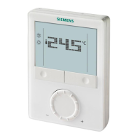
RDG100…
1- or 3-speed fan
Application
V1
V2
2-pipe
YHC
2-pipe & radiator
4-pipe
2-stage
YHC
YH
1st
YR
YC
2nd
2-pipe & el. heater
YHC
E1
4-pipe & el. heater
YH
E1
YC
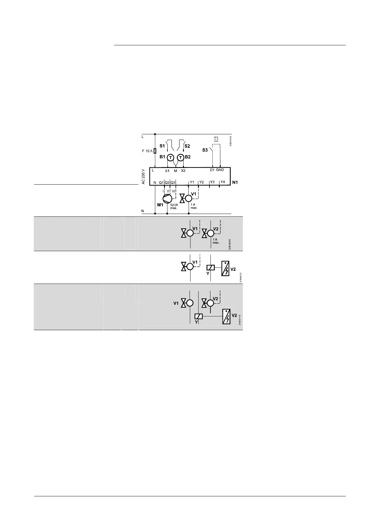
N1 Room thermostat RDG100..
M1 1- or 3-speed fan
V Valve actuators:
ON/OFF or PWM, 3-position,
heating, cooling, radiator,
heating / cooling, 1st or 2nd
stage
E1 Electric heater
S1, S2 Switch (keycard, window
contact, etc.)
S3 Switch at SELV input (keycard,
window contact)
B1, B2 Temperature sensor (return air
temperature, external room
temperature, changeover
sensor, floor temperature limit,
etc.)
Q Relay outputs
Y1...Y4 Triac outputs
YH Heating valve actuator
YC Cooling valve actuator
YHC Heating / cooling valve
actuator
YR Radiator valve actuator
E1 Electric heater with relay /
contactor Y
1
st
/ 2
nd
1
st
/ 2
nd
stage
Note

 Loading...