4.2 Terminal assignment
Denition
The pin assignment provides information about the arrangement and marking of the
connections when wiring the terminal block.
Description
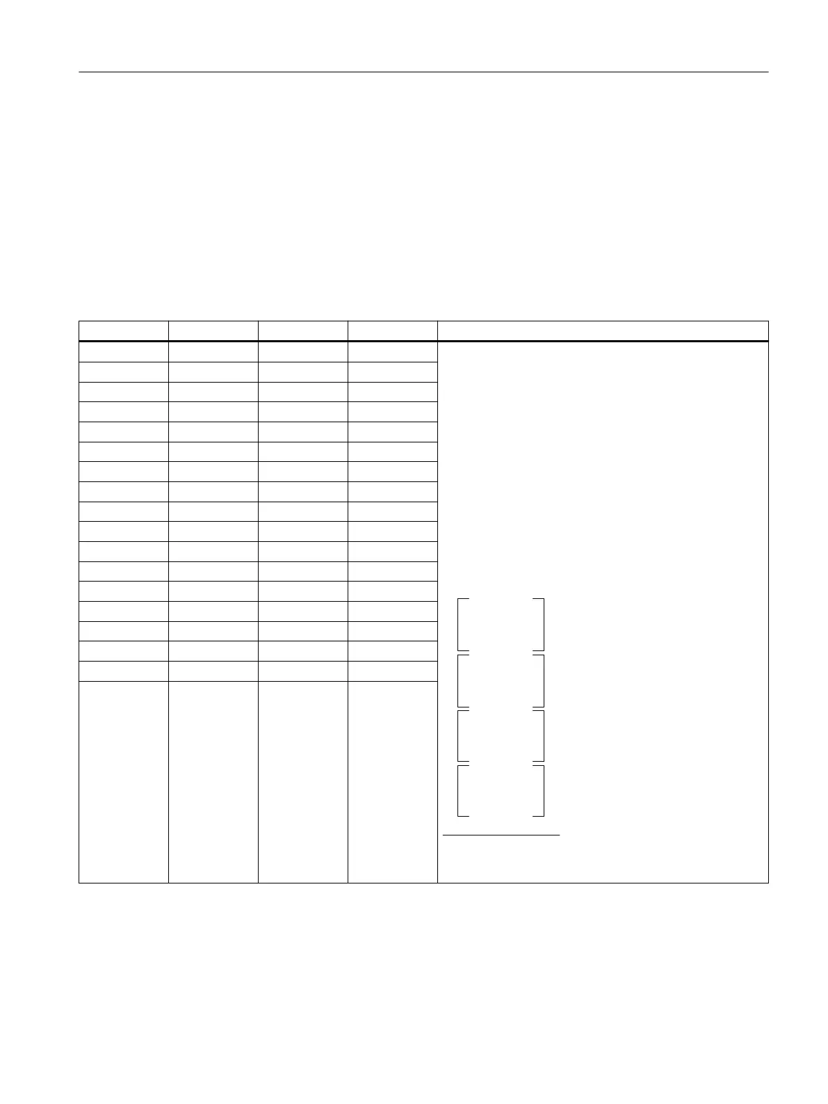
The pin assignment is structured as follows:
Terminal Assignment Terminal Assignment Explanations
1 UV0 2 UV1
• Terminal 1 to 8:
UVn: Sensor supply, channel n
• Terminal 9 to 16:
In+: Current input positive, channel n
• Terminal 17 to 24:
In-: Current input negative, channel n
• Terminal 25 to 32:
Mn: Ground; channel n
1P1: Supply voltage L+ of the voltage bus 1P
2P1: Supply voltage L+ of the voltage bus 2P
1P2: Ground reference of the voltage bus 1P
2P2: Ground reference of the voltage bus 2P
.
.
1
-7%$.
1
1
-7%$.
1
."9"
*
*
*
*
*
*
*
*
.
.
.
.
.
.
67
67
67
67
67
67
67
67
"*XJSF"*XJSF
*
*
*
*
*
*
*
*
3 UV2 4 UV3
5 UV4 6 UV5
7 UV6 8 UV7
9 I0+ 10 I1+
11 I2+ 12 I3+
13 I4+ 14 I5+
15 I6+ 16 I7+
17 I0- 18 I1-
19 I2- 20 I3-
21 I4- 22 I5-
23 I6- 24 I7-
25 M0 26 M1
27 M2 28 M3
29 M4 30 M5
31 M6 32 M7
1P1 L+ 1P2 M
2P1
1
L+ 2P2 M
1
If the module is inserted in a TB45R-P32+A0+4D terminal block (6DL1193-6TP00-0DF1) suitable for IO redundancy, the
potential at this terminal is 1P3.
Connection
4.2 Terminal assignment
F-AI 8xI 2-/4-wire HART HA
Equipment Manual, 09/2021, A5E50557845-AA 17

 Loading...