Technical Appendix
6.2 PLC user interface signals
6-105
SINUMERIK 802C
6FC5 597–3AA20–0BP2 (01.02)
Technical Appendix
6.2 PLC user interface signals
The following tables of the user interface signals between PLC and NC (and vice versa) are
handled by the integrated fixed user program.
These signals can be displayed using PLC Status in the Diagnosis/Start–Up/PLC Status
menu.
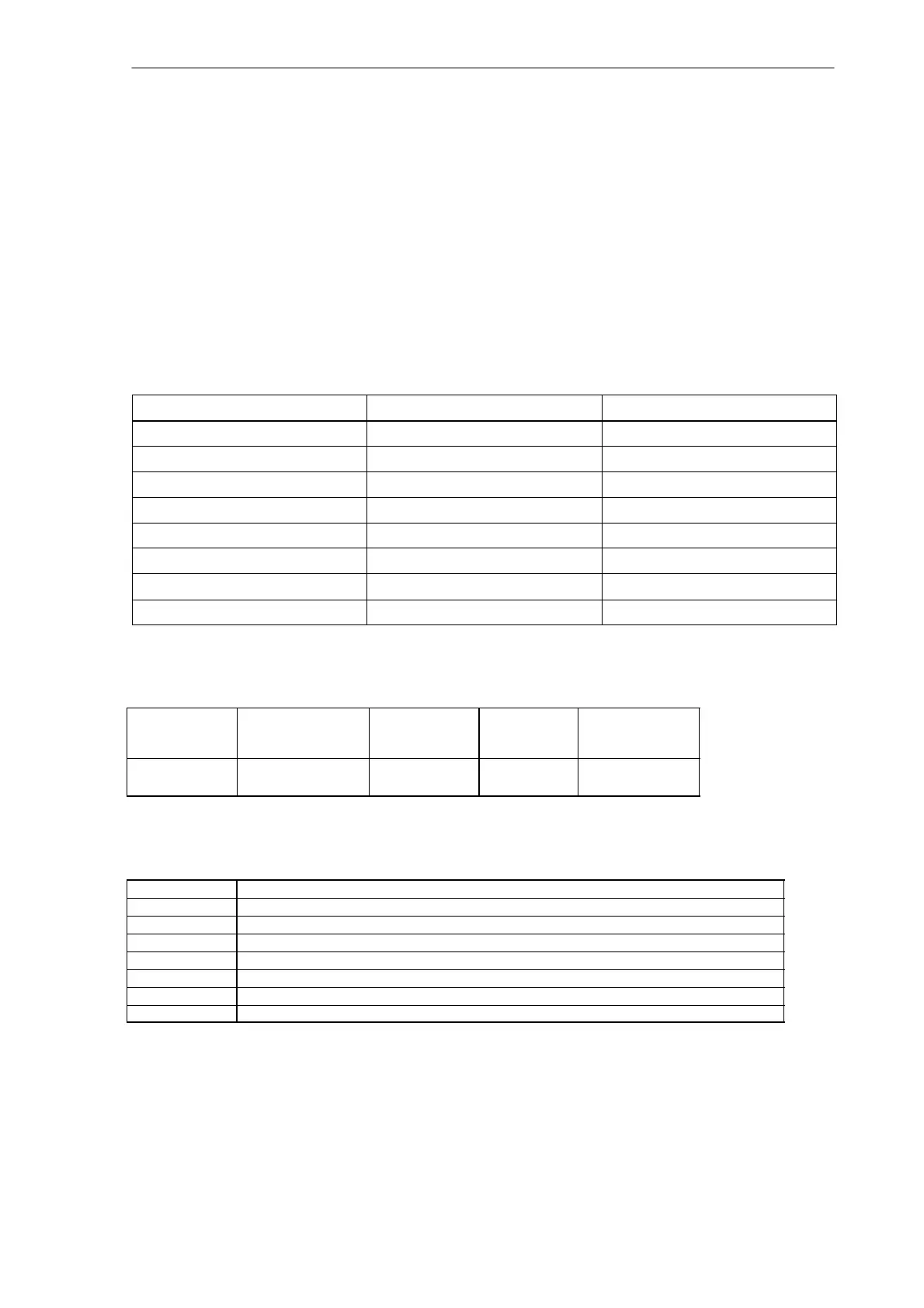
6.2.1 Address ranges
Operand Identifier Description Range
V Data V0.0 to V79999999.7 (see below)
T Timers T0 to T15
C Counters C0 to C31
I Image of digital inputs I0.0 to I7.7
Q Image of digital outputs Q0.0 to Q7.7
M Flags M0.0 to M127.7
SM Special flags SM0.0 to SM 0.6 (see below)
AC ACCU AC0 ... AC3
Generating the V address range
Type
Identifier
(DB No.)
Range No.
(Channel /
Axis No.)
Subrange Offset Addressing
10
(10-79)
00
(00-99)
0
(0-9)
000
(000-999)
symbolic
(8-digit)
Definition of special flag bits (SM) (read–only)
SM Bits Description
SM 0.0 Flags with a defined ONE signal
SM 0.1 Initial position: first PLC cycle ‘1’, following cycles ‘0’
SM 0.2 Buffered data lost - only valid in the first PLC cycle (‘0’ - data o.k., ‘1’ - data lost)
SM 0.3 Power On: first PLC cycle ‘1’, following cycles ‘0’
SM 0.4 60 s clock (alternating ‘0’ for 30 s, then ‘1’ for 30 s)
SM 0.5 1 s clock (alternating ‘0’ for 0.5 s, then ‘1’ for 0,5 s)
SM 0.6 PLC cycle clock (alternating one cycle ‘0’, then one cycle ‘1’)

 Loading...


