Installing the Control System
2.2 Interfaces and cables
2-18
SINUMERIK 802C
6FC5 597–3AA20–0BP2 (01.02)
2.2 Interfaces and cables
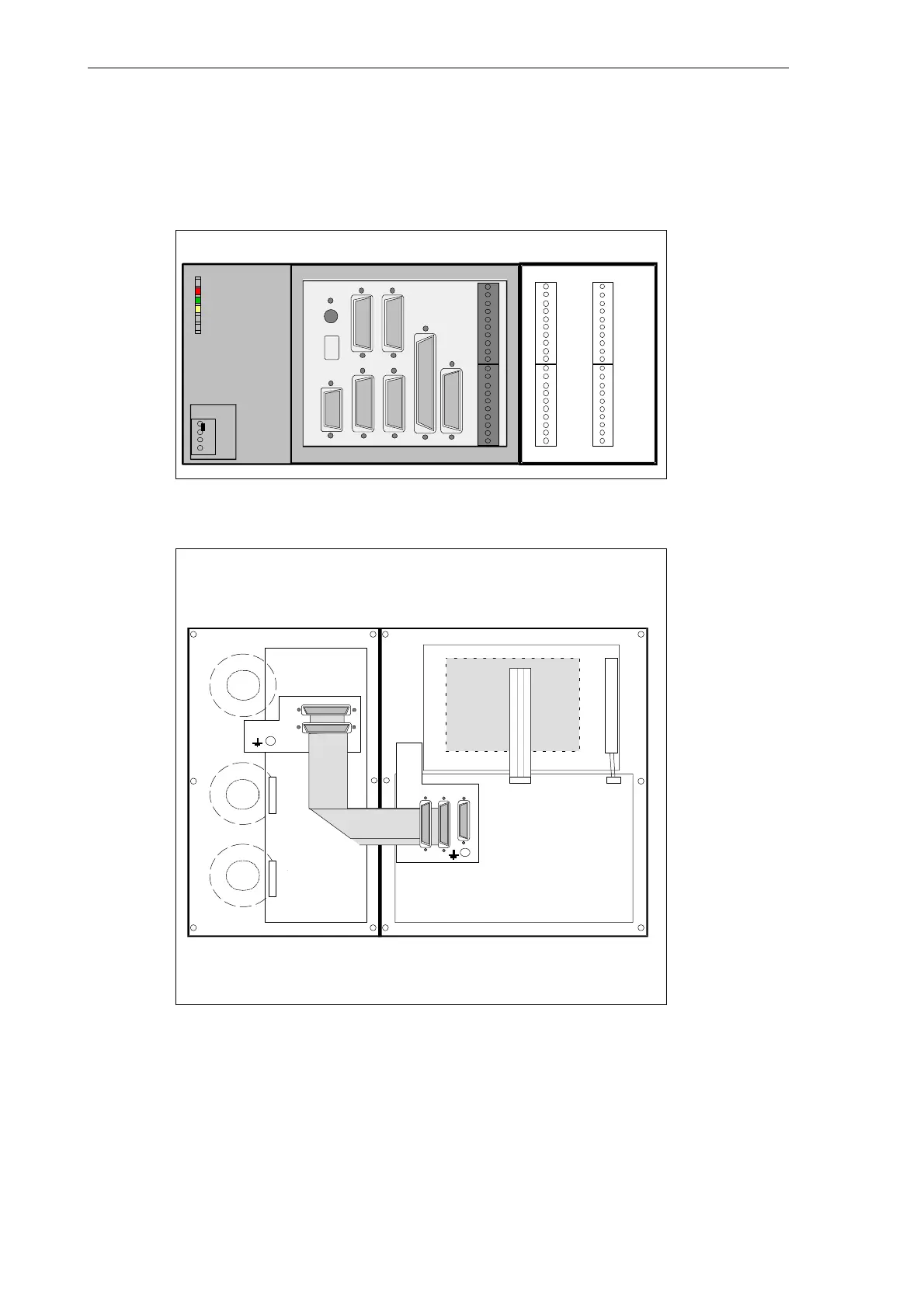
Position of the interfaces and front panel elements
X2003 X2005
X2004 X2006
0
1
2
3
4
5
6
7
M
L+
0
1
2
3
4
5
6
7
M
8
9
10
11
12
13
14
15
M
L+
8
9
10
11
12
13
14
15
M
IN
OUT
ECU DI/O16
DC24V X1
RS232
X2
SPINDLE
X5
ENCODER3
X6
OPI
X8
AXIS
X7
X10
MPG
DI
X20
ERR
DIAG
POK
PE
L+
M
M
ENCODER2
X4
ENCODER1
X3
S2
S3
D15
Fig. 2-2 User interfaces
OP020
MCP
LCD- signal
connector
Rear
Rear
X1001 X1002 X1009
X1202
X1201
CFL
Fig. 2-3 Rear of machine control panel and operator panel

 Loading...


